
Vertical pixel structures for emi-flective display and methods for making the same

a technology of emi-flection display and vertical pixel structure, which is applied in the direction of semiconductor devices, electrical devices, instruments, etc., can solve the problems of reduced image quality of display, increased power consumption, and inability to increase the aperture of display, so as to achieve optimum energy saving, increase the effect of cost and increase the apertur

Inactive Publication Date: 2007-02-08
IND TECH RES INST
View PDF5 Cites 26 Cited by
  • Summary
  • Abstract
  • Description
  • Claims
  • Application Information

AI Technical Summary

Benefits of technology

[0008] An object of the present invention is to provide a pixel structure for a vertical emissive-reflective (emi-flective) display that can solve lower aperture and high power consumption of the conventional horizontal emi-flective display.
[0009] Another object of the present invention is to provide a pixel structure for a vertical emi-flective display and a method thereof that are compatible with the current manufacturing processes for thin film transistor (TFT) array, organic light-emitting diode (OLED) and liquid crystal. Therefore, no additional masks are required and the cost can be decreased.
[0010] Another object of the present invention is to provide a pixel structure for a vertical emi-flective display and a method thereof. The method requires no wet processing, and therefore the yield can be increased.
[0022] In accordance with the foregoing vertical pixel structures and the methods thereof, a display with a higher aperture can be provided and the display can have an optimum energy saving. In addition, the display is suitable for displays of indoor and outdoor types. In addition, the manufacturing methods of the present invention are compatible with the processes of manufacturing TFT array, OLED and LCD without increasing costs. Moreover, since no wet processes are required, the yield can be increased.

Problems solved by technology

As a result, the aperture of the display cannot be increased, and therefore, the image quality of the display is decreased.
When the conventional horizontal emi-flective display is used, its power consumption is higher because a backlight module is also required for half transmissive mode.
At the same time, because of having a horizontal structure, the aperture of the display cannot be increased.
However, the aforementioned display has a problem that its aperture cannot be increased.
This structure also has drawbacks of low aperture and high power consumption.

Method used


Image

  • Vertical pixel structures for emi-flective display and methods for making the same
  • Vertical pixel structures for emi-flective display and methods for making the same
  • Vertical pixel structures for emi-flective display and methods for making the same

Examples


Embodiment Construction

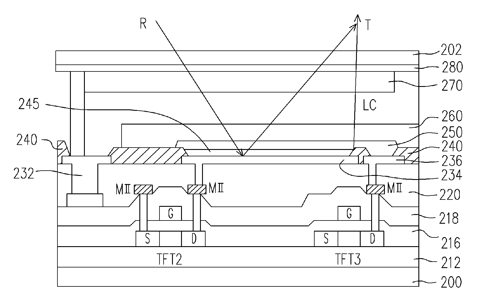
[0031] Technical features of the present invention will be further described in detail in accordance with the attached drawings. The concept of the present invention is to arrange a self-light emitting display unit and a reflective-type display unit vertically on a substrate.

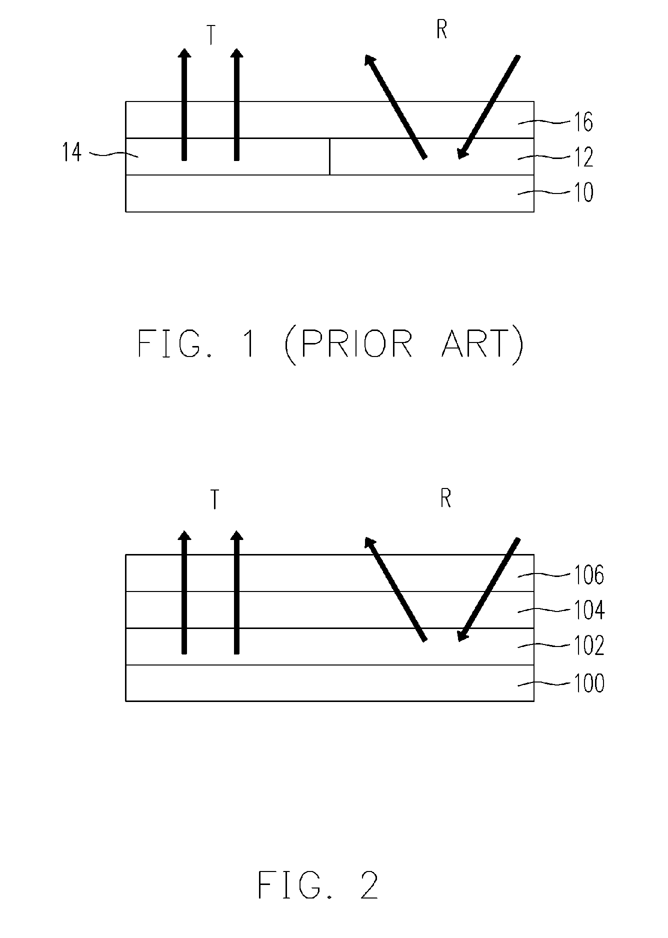
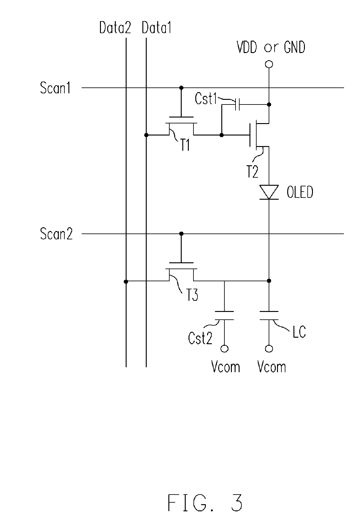
[0032]FIG. 2 is a schematic diagram showing a pixel structure for a vertical emissive-reflective (emi-flective) display according to the present invention. A single pixel is used as an example for detail description, but for a complete panel, there are same pixel structures on the substrate. In addition, the term “emi-flective” mentioned in the present invention relates to a pixel structure having s self-light emitting display unit and a reflective-type display unit.

[0033] As shown in FIG. 2, the pixel for the emi-flective display of the present invention is also established on a substrate 100. The substrate 100 is, for example, a flexible substrate. Furthermore, the substrate 100 can be a glass, plastic, sili...


PUM


Abstract

A vertical pixel structure for emi-flective display and a method thereof are provided. The vertical pixel structure has a substrate, a emitting pixel unit arranged on the substrate and a reflective pixel unit arranged on the emitting pixel unit. By using the vertical pixel structure the aperture of the display can be increased, and the power consumption can be reduced as well.

Description

CROSS-REFERENCE TO RELATED APPLICATION [0001] This application claims the priority benefit of Taiwan application Ser. No. 94126311, filed on Aug. 3, 2005. All disclosure of the Taiwan application is incorporated herein by reference. BACKGROUND OF THE INVENTION [0002] 1. Field of the Invention [0003] The present invention relates to pixel structures of a display, and more particularly to a vertical pixel structure for an emi-flective (emitting-reflective) display and a fabricating method thereof. [0004] 2. Description of Related Art [0005]FIG. 1 illustrates a pixel structure for a conventional emissive-reflective (emi-flective) display. The pixel structure includes a substrate 10, a self-light emitting pixel unit 14, a reflective pixel unit 12, and a transparent cover layer 16. The pixel structure is a horizontal type. Namely, the self-emitting pixel unit 14 and the reflective pixel unit 12 are disposed on the left and right sides of the same plane. As a result, the aperture of the d...

Claims


Application Information

Patent Timeline
Patent Type & Authority Applications(United States)
IPC IPC(8): H01L21/84H01L21/00
CPCG02F1/133555G02F1/1362G09G3/3208G09G3/3225G09G3/3648H01L51/0541G09G2300/046G09G2300/0465G09G2300/0852H01L27/12G09G2300/023H10K10/464
Inventor YEH, YUNG-HUIWANG, YU-WULIU, YU-LUNGLIAO, CHI-CHANGWANG, HSING-LUNG
Owner IND TECH RES INST
Learn More