Connection terminal and a connection terminal assembly and method for assembling the connection terminal

a technology of connection terminals and assembly methods, applied in the direction of incorrect coupling prevention, coupling device connection, electrical apparatus, etc., can solve the problems of increasing cost, complex assembly process, and difficulty in positioning the terminal, so as to avoid the increase in cost and facilitate positioning

Inactive Publication Date: 2007-02-08
HITACHI LTD
View PDF11 Cites 9 Cited by
  • Summary
  • Abstract
  • Description
  • Claims
  • Application Information

AI Technical Summary

Benefits of technology

[0011] It is therefore an object of the present invention to provide a fitting-type connection terminal, which secures easy

Problems solved by technology

For this reason, the contact portion or connecting portion have to be gold plated, but this leads to an increase in cost.
On the other hand, when using the above-mentioned fitting-typ

Method used


Image

  • Connection terminal and a connection terminal assembly and method for assembling the connection terminal
  • Connection terminal and a connection terminal assembly and method for assembling the connection terminal
  • Connection terminal and a connection terminal assembly and method for assembling the connection terminal

Examples


embodiment 1

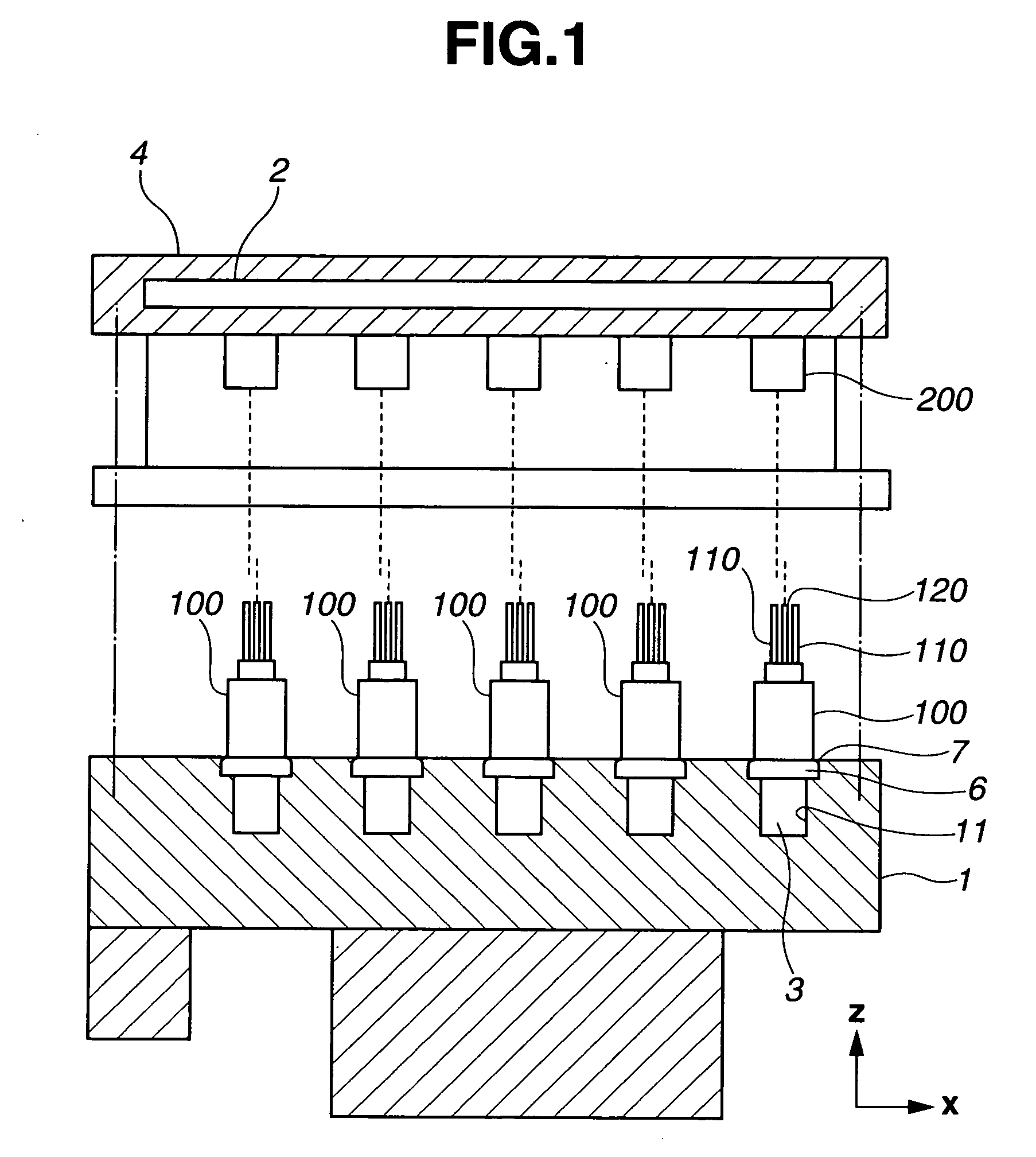
[0051] Embodiments of the present invention will be explained below with reference to the drawings. Firstly, an embodiment 1 will be explained with reference to FIGS. 1 to 19. FIG. 1 is a local sectional view of a brake device using a connection terminal according to the present invention. The brake device employs a hydraulic circuit housing 1 (a first housing, or simply, a housing), an electrical control unit (ECU) board 2 (a connected member) that faces hydraulic circuit housing 1, a male connector 100 (a first assembly), and a female connector 200 (a second assembly). In FIG. 1, a direction from hydraulic circuit housing 1 toward ECU board 2 (this direction is a connecting direction of a connection terminal in the present invention) is defined as z-axis, an axis orthogonal to z-axis and parallel to the drawing is defined as x-axis, and a direction normal to the drawing is defined as y-axis.

[0052] Hydraulic circuit housing 1 is formed by aluminum die casting. And a hydraulic circu...

case 140

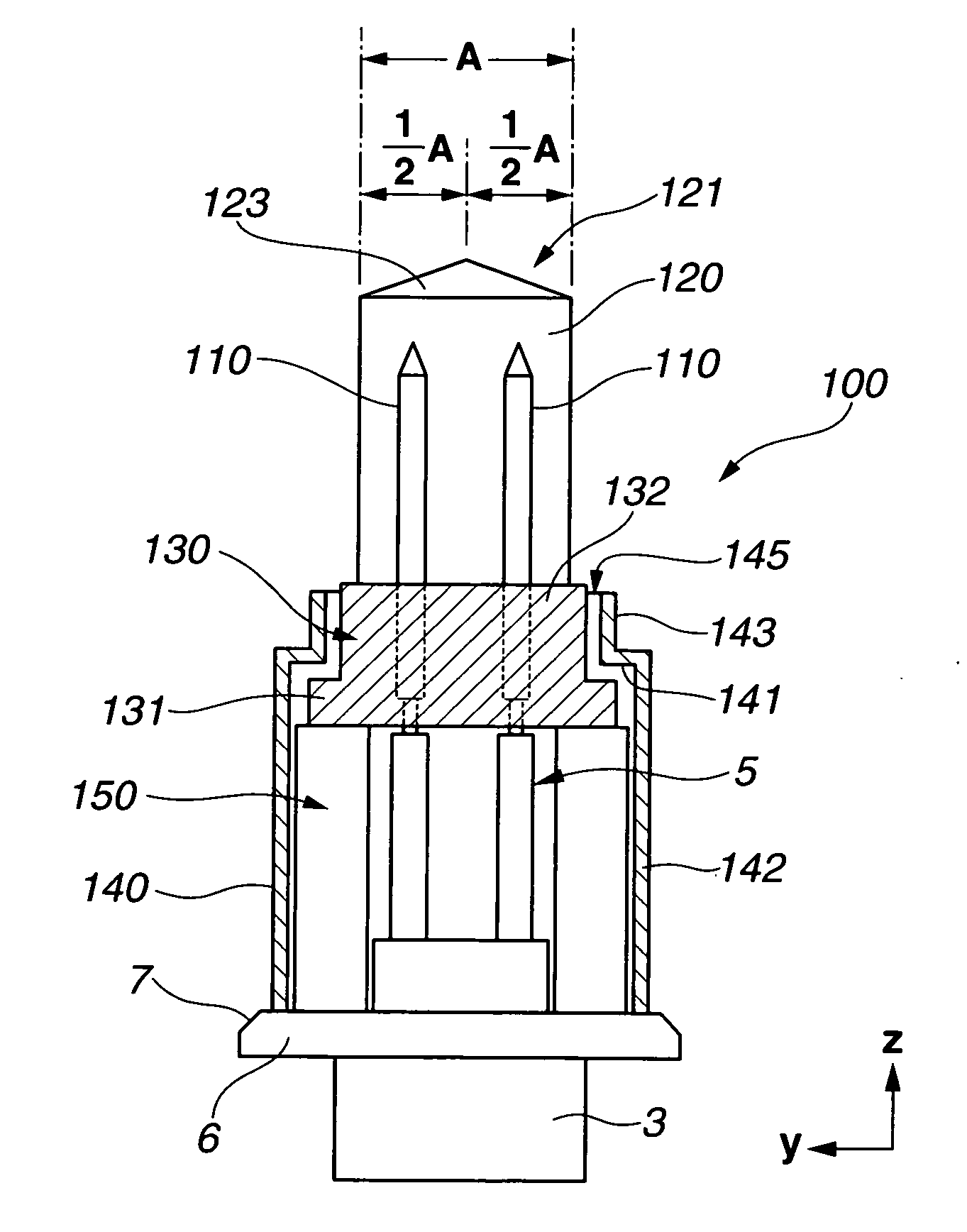
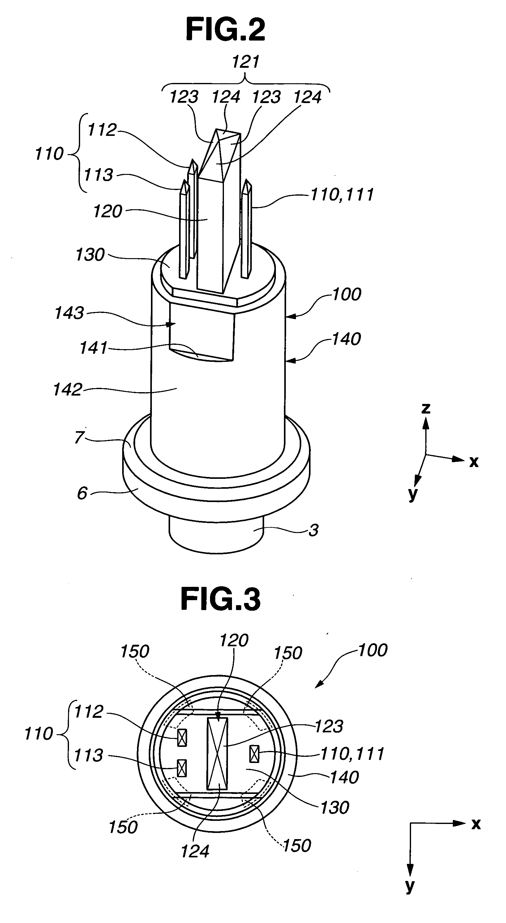
[0067] Case 140, which is substantially cylindrical in shape, has a step or stepped portion 141 (a limiting or limitation portion that limits movement in a terminal stage installation direction of terminal stage 130) at an upper end portion (or positive direction side end portion) in z-axis direction of case 140. Further, case 140 has a cylindrical portion 142 that is positioned below the stepped portion 141, and a hollow elongated hole portion 143 that is positioned above the stepped portion 141. Cylindrical portion 142 is substantially cylindrical in shape. As for hollow elongated hole portion 143, it is elongated hole in shape, which is cut off at circumferentially-opposed arcs of case 140 along z-axis direction in the same manner as projecting portion 132 of terminal stage 130. And an opening portion 145 of hollow elongated hole portion 143 is opened in the positive direction of z-axis as being the shape. That is to say, case 140 is formed of stepped portion 141, cylindrical por...

embodiment 4

[0109] In the embodiment 4, guide 120′ of male connector 100′ is formed into cylindrical shape. Male terminal 110′ is also formed into cylindrical shape. Further, male terminal 110′ tapers to a point at the top. At periphery of terminal stage 130′, as shown in FIG. 27, a rotation stopper receiving portion 133′ is provided as an anti-rotation mechanism. This rotation stopper receiving portion 133′ is formed by cutting away circumferentially-opposed arcs of outer periphery of terminal stage 130′ from the positive direction of z-axis such that rotation stopper receiving portion 133′ is recessed radially inward and downward.

[0110] Although the detail of the anti-rotation mechanism will be explained later, the rotation of a certain rotation amount or more of terminal stage 130′ is limited by means of rotation stopper receiving portion 133′ and a rotation stopper portion 141′ (see FIGS. 29, 30) that is provided for a case 140′. Here, in this embodiment, two rotation stopper receiving port...


PUM


Abstract

A connection terminal includes a housing, a case fixed to the housing, a terminal stage installed inside the case and having a first terminal and a guide portion, the first terminal and the guide portion projecting parallel to each other from one end of the terminal stage in the same direction, a connected member facing the case and having a second terminal to which the first terminal is fitted and connected for establishment of electrical connection, and a recessed portion to which the guide portion is fitted. The terminal stage is movable at least in a direction orthogonal to a direction of the connection between the first and second terminals while being installed inside the case. The first and second terminals are fitted to each other after the guide portion is fitted to the recessed portion.

Description

BACKGROUND OF THE INVENTION [0001] The present invention relates to a connection terminal, and more particularly to a connection terminal assembly that connects a fluid pressure sensor and a control circuit board. [0002] In connection terminals which connect fluid pressure sensors and control circuit boards, there has been a connection terminal (a fitting-type connection terminal) that achieves an electrical contact between a male terminal and a female terminal by fitting the male terminal into the female terminal. In this connection terminal, the male terminal is an axial member formed with electric conductor such as metal, and the male terminal is inserted and fitted into the female terminal. The connection terminal, therefore, ensures electrical conductivity. [0003] Generally, the connection terminal is not so large, therefore, an axial diameter of the male terminal tends to be small, or an axis of that tends to be thin. Further, a length of the axis of male terminal is substanti...

Claims


Application Information

Patent Timeline
IPC IPC(8): H01R13/64
CPCH01R13/6315
Inventor TAKAGI, KATSUYUKI
Owner HITACHI LTD
Why Eureka
Try Eureka