
Hydraulic chain tensioner assembly

a technology of chain tensioner and assembly, which is applied in the direction of belt/chain/gearing, mechanical equipment, belts/chains/gearings, etc., can solve the problems of chain slackening, rattle or clatter noise of chain impacting against the sprockets and guides, and achieves low applied load, minimize whine and whiz noise, and reduce the effect of reactive load

Inactive Publication Date: 2007-02-08
GM GLOBAL TECH OPERATIONS LLC
View PDF8 Cites 36 Cited by
  • Summary
  • Abstract
  • Description
  • Claims
  • Application Information

AI Technical Summary

Benefits of technology

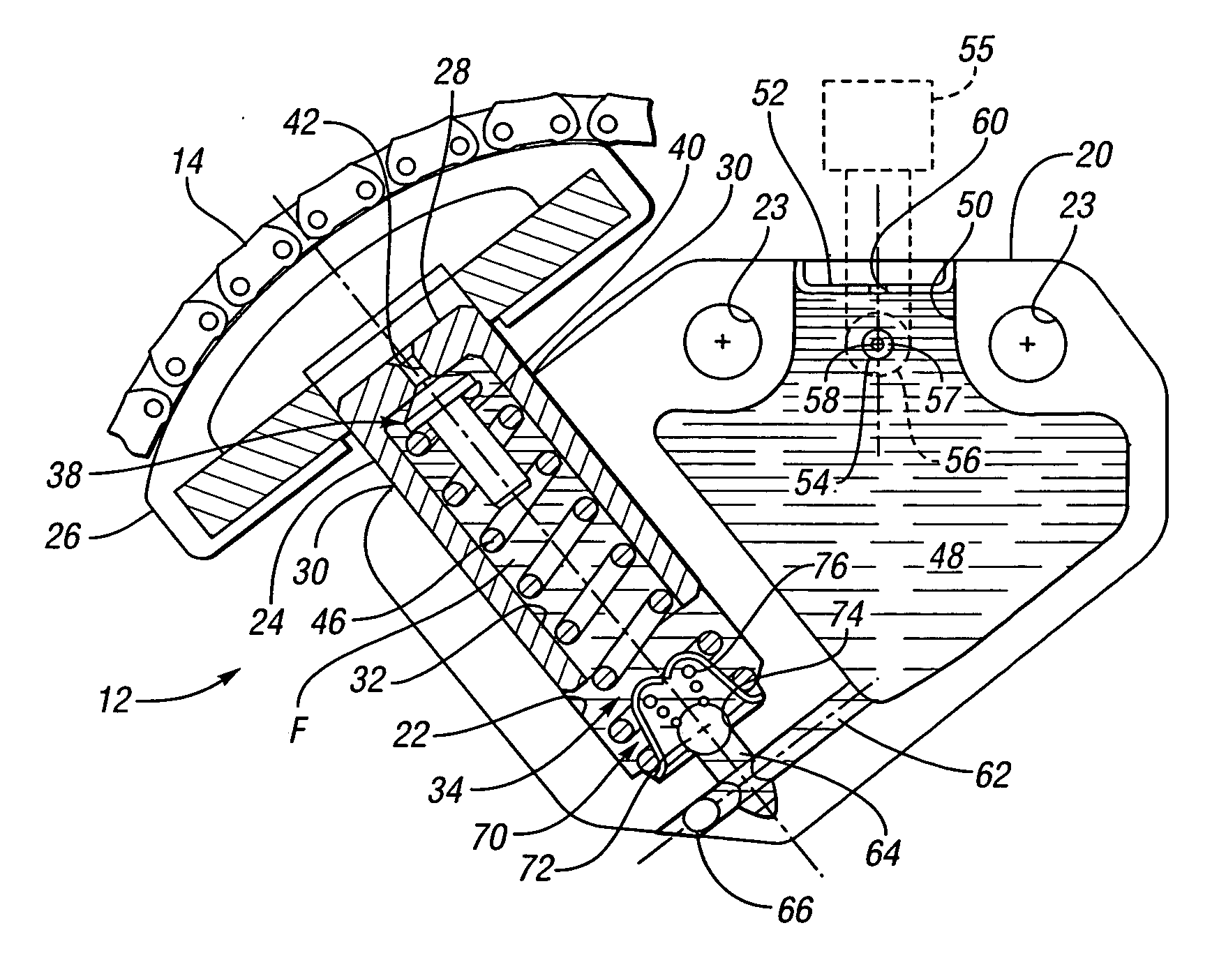
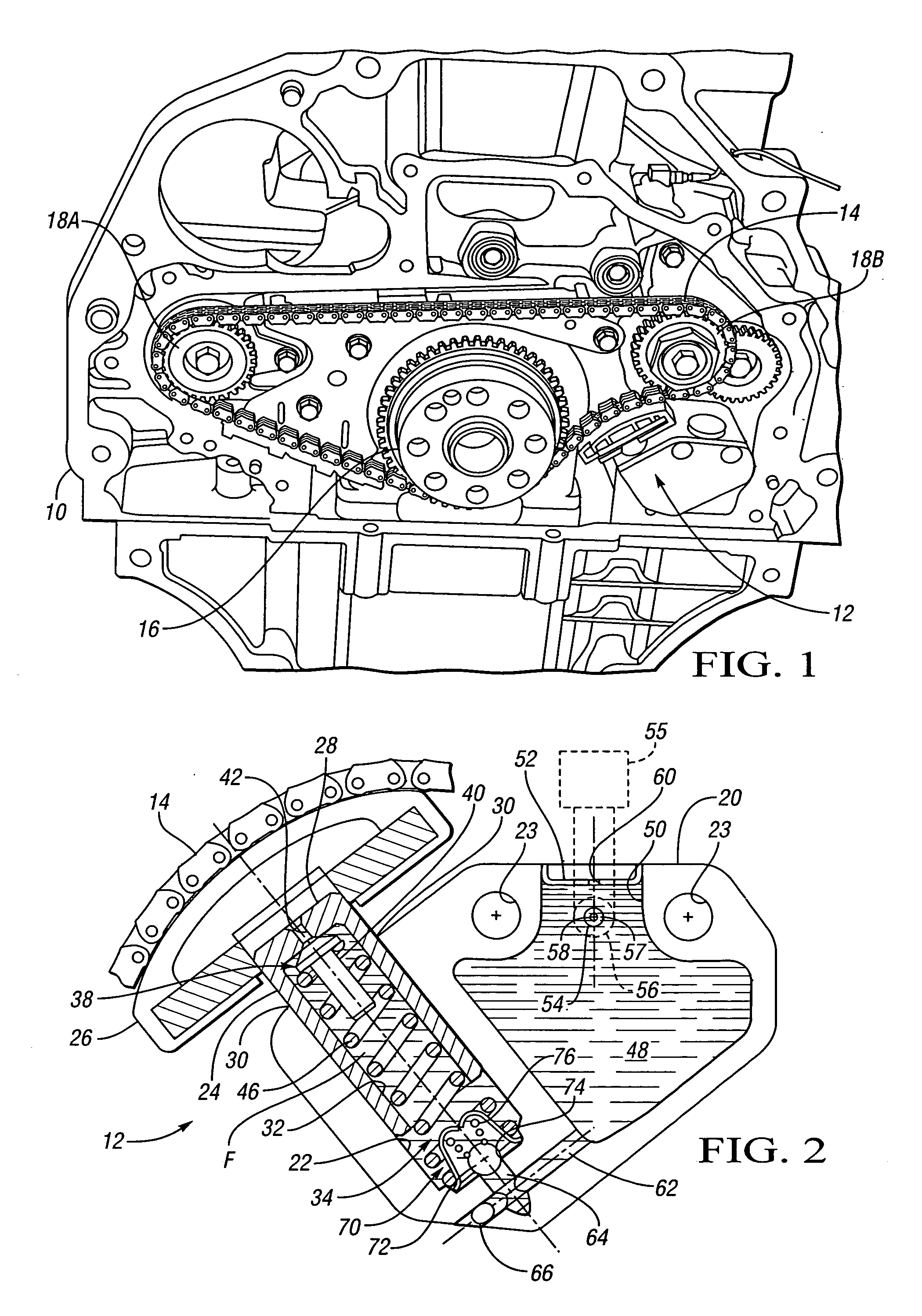
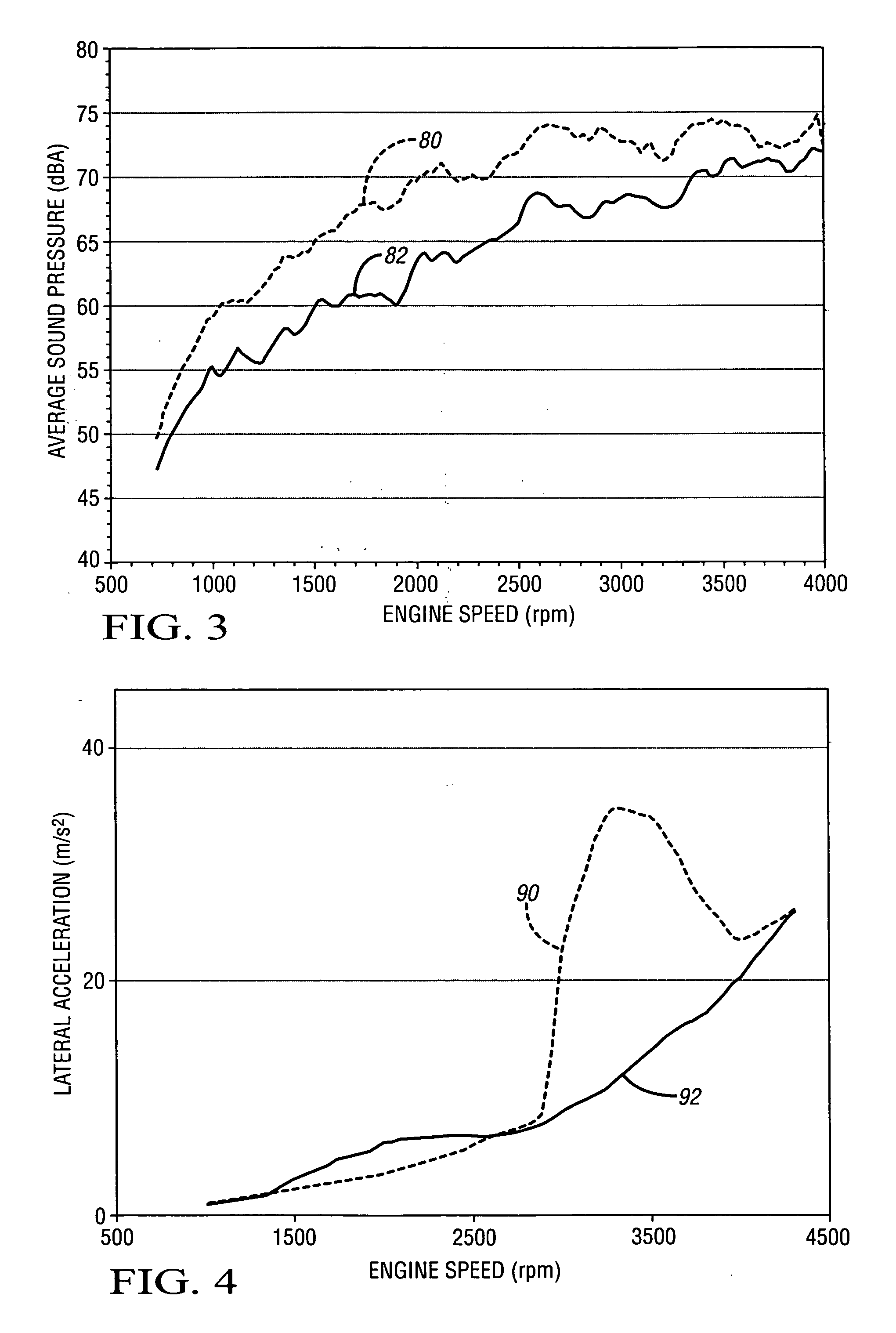
[0003] A hydraulic chain tensioner assembly is provided that achieves low apply loads to minimize whine and whiz noise but is very stiff in reactive loading, which maintains control of the chain while minimizing clatter or rattle type noise.
[0007] In one aspect of the invention, an air vent valve is in communication with the fluid chamber to vent air therefrom, thereby causing the fluid column within the chamber to be substantially air-free and to have a hydraulic stiffness that substantially prevents inward movement of the shoe when under loading by the chain. Preferably, the air vent valve is a piddle valve which enables air, but not the more viscous fluid within the chamber, to vent therefrom.
[0010] In one aspect of the invention, the check valve permits flow into the fluid chamber when the plunger moves outward, which occurs when force from the spring overcomes force of the chain against the shoe. Additionally, the clearance, check valve and air vent valve permit the fluid-filled chamber to provide a substantially static reaction load when loaded by the chain. This is possible because the clearance between the plunger and the opening is preferably so small that the leak down time of the plunger is extremely long. Thus, the hydraulic chain tensioner assembly supplies a relatively low apply force to take up slack from the chain, the apply force not being influenced by system pressure, and yet provides a very stiff reaction load.

Problems solved by technology

Over time, a chain may slacken due to repeated loading and unloading cycles during torque reversal.
When tensioner reaction loads are too low, a rattle or clatter noise of the chain impacting against the sprockets and guides occurs.

Method used


Image

  • Hydraulic chain tensioner assembly
  • Hydraulic chain tensioner assembly
  • Hydraulic chain tensioner assembly

Examples


second embodiment

[0032] Referring to FIG. 5, a hydraulic chain tensioner assembly 112 is shown. Attachment hole openings 123 are drilled or otherwise formed in the tensioner body 120 for receiving attachment mechanisms such as bolts to attach the hydraulic chain tensioner assembly 112 to an engine as in well understood by those skilled in the art. The hydraulic chain tensioner assembly 112 includes a tensioner body 120 having an opening or bore 122 with a plunger 124 slideably received therein to define a fluid-tight chamber 134, with a main spring 146 biasing the plunger 124 outward. The plunger 124 and the opening 122 are relatively sized to define a controlled diametral clearance 130 therebetween that is on the order 2 to 8 μm, thereby establishing the fluid tightness of the chamber 134. A fluid column F′ within the chamber 138 extends between the bottom of the plunger 124 and the bottom end of the bored opening 122, on which the spring 146 is seated. The plunger 124 defines an internal reservoir...

third embodiment

[0035] Referring to FIG. 6, a hydraulic chain tensioner assembly 212 is depicted. Tensioner body 220 has an opening 222 or bore which receives a slideable plunger 224 therein. A shoe 226, plunger 224, air vent valve 238, and a main spring 246 are similarly constructed as like components in FIG. 2. Additionally, a supply reservoir 248 having a feed port 254 with a feed port cup plug 257 and a feed orifice 258 therein positioned at a fluid supply passage 256, as well as a cup plug 252 with a bleed orifice 260 therein are similarly constructed as like components of FIG. 2. Attachment hole openings 223 are drilled or otherwise formed in the tensioner body 220 for attaching the hydraulic chain tensioner assembly 212 to an engine.

[0036] Unlike the opening of bore 22 of FIG. 2, the opening 222 of FIG. 6 is bored completely through the tensioner body 220. A plug 225 is pressed in an end of the opening 222 opposite the shoe 226 to close off the opening 222 thereby defining with the opening 2...


PUM


Abstract

A hydraulic chain tensioner assembly includes a plunger slider received within an opening in a tensioner body to define a controlled clearance and a substantially fluid-tight chamber. Pressure in a supply reservoir that is in fluid communication with the fluid-tight chamber is controlled to a relatively low level by appropriate sizing of the feed orifice and a bleed orifice in communication with the supply reservoir. Thus, apply force of a shoe connected to a plunger on a chain is a function of stiffness of a main spring that biases the plunger outward, and is not substantially affected by pressure of a fluid source supplying fluid to the reservoir. A method of manufacturing a hydraulic chain tensioner assembly is also provided.

Description

TECHNICAL FIELD [0001] This invention relates to a hydraulic chain tensioner assembly including a fluid-tight chamber connected to a pressure-controlled supply reservoir. BACKGROUND OF THE INVENTION [0002] The chain drive has emerged as the preferred means of operating ancillary components within the modern automotive engine. For example, chain drives have been employed to drive complex valve trains, balance shafts, oil pumps, high pressure fuel injection pumps and water pumps. A dedicated tensioning device has become a virtual necessity to ensure the overall functional performance of a chain drive given the advent of increasing packaging complexity and its influence on chain drive layout and design. Over time, a chain may slacken due to repeated loading and unloading cycles during torque reversal. Hydraulic chain tensioner assemblies must strike a balance in imposing an apply force sufficient to tighten a slack chain to ensure chain functionality, while minimizing chain noise. Nois...

Claims


Application Information

Patent Timeline
Patent Type & Authority Applications(United States)
IPC IPC(8): F16H7/08F16H7/22
CPCF16H7/0848F16H2007/0859F16H2007/0812F16H2007/0806
Inventor BEARDMORE, JOHN M.
Owner GM GLOBAL TECH OPERATIONS LLC
Learn More