Coated ceramic total joint arthroplasty and method of making same

Inactive Publication Date: 2007-02-08
WHITESIDE LEO A
View PDF38 Cites 43 Cited by
  • Summary
  • Abstract
  • Description
  • Claims
  • Application Information

AI Technical Summary

Benefits of technology

[0014] An ideal joint replacement implant would have a very hard and strong substrate material with stable structure, and a highly inert surface that produces extremely low wear and low friction, but does not have the

Problems solved by technology

However, particularly in knee and hip replacements, problems involving wear persist.
The most common cause of failure in modern total hip replacement is wear of the articulating bearing surfaces.
The metal can be highly polished, but it oxides as time passes, and thus roughens and releases highly abrasive oxide particles and carbide particle inclusions into the joint.
Improvements in the polyethylene, such as cross-linking and compression molding, have improved the metal-on-polyethylene bearing surfaces, but the time related deterioration of the metal surface continues to limit the effectiveness of these types of implants, especially in young, active patients.
However, the ceramic surface can also deteriorate and roughen as it ages.
Although these oxidized zirconium surfaces are more resistant to wear and corrosion than metal surfaces, and are stronger than standard ceramic implants, they have the disadvantage of being susceptible to scratching by third body particles.
However, these metal-on-metal articulation surfaces release potentially toxic metal ions and occasionally are subjected to high friction and wear.
However, the strength of alumina ceramic is a clinical problem, and has not been completely solved.
Moreover, making alumina ceramic femoral heads for total hip replacement appliances in smaller sizes, and using alumina (and other ceramic materials) in thin components for fitting smaller hips is not practical because of the poor tensile strength of this material.
Also, alumina ceramic can lose crystals from its surface.
These alumina ceramic crystals are very hard and abrasive and can lead to accelerated third-body wear and catastrophic failure.
However, zirconia ceramics have had a problem with composition leading to late surface roughening, fracture, and catastrophic failure.
This creates a roughening of the

Method used


Image

  • Coated ceramic total joint arthroplasty and method of making same
  • Coated ceramic total joint arthroplasty and method of making same
  • Coated ceramic total joint arthroplasty and method of making same

Examples


Embodiment Construction

[0064] The following detailed description illustrates the disclosure by way of example and not by way of limitation. This description will clearly enable one skilled in the art to make and use the disclosure, and describes several embodiments, adaptations, variations, alternatives and uses of the disclosure, including what I presently believe is the best mode of carrying out the disclosure. Additionally, it is to be understood that the disclosure is not limited in its application to the details of construction and the arrangements of components set forth in the following description or illustrated in the drawings.

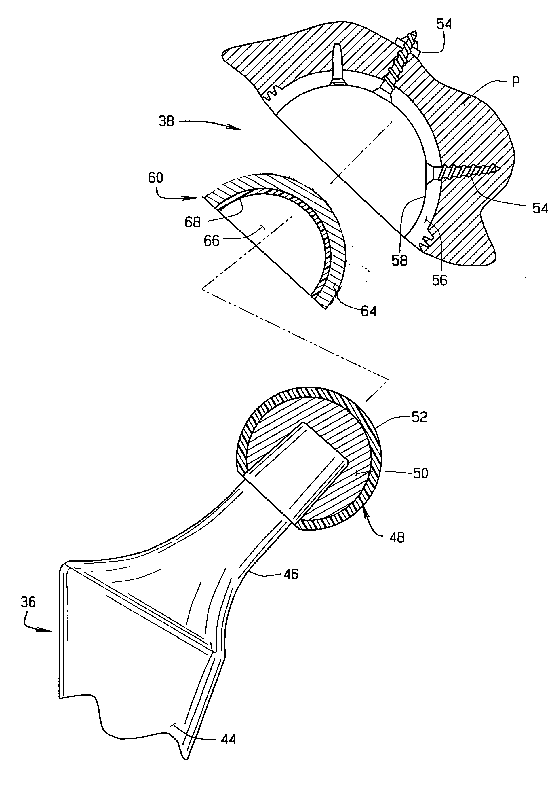
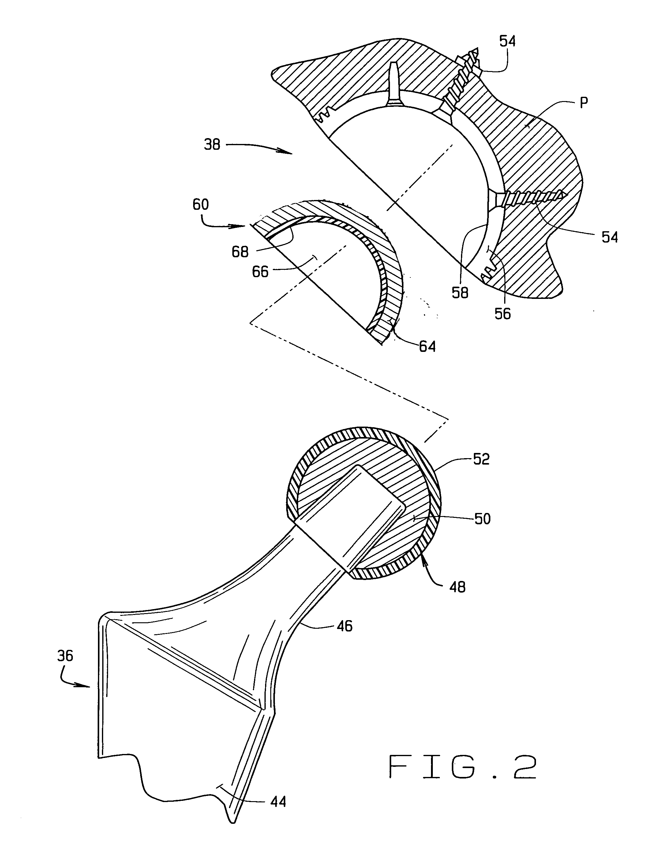
[0065] As will be apparent to those skilled in the art of designing total arthroplasty joints, the present disclosure is capable of other embodiments and of being practiced or being carried out in joints other than hip and knee joints. Specifically, while the present disclosure is described in the environment of total hip and knee replacement joints, those skilled in the a...


PUM

PropertyMeasurementUnit
Pressureaaaaaaaaaa
Pressureaaaaaaaaaa
Pressureaaaaaaaaaa

Abstract

A total joint arthroplasty is described having a first bearing member (e.g., the femoral head of the femoral component of a total arthroplasty hip joint) and a second bearing member (e.g., an acetabular component) cooperable with the first bearing member with the articulating surfaces of the bearing members in engagement with one another, and wherein at least one of the bearing members has a substrate of a magnesia-stabilized zirconia ceramic material and a bearing surface having a carbon coating applied to the bearing surface.

Description

CROSS-REFERENCE TO RELATED APPLICATIONS [0001] This application claims priority under 35 U.S.C. § 119(e) of U.S. Provisional Patent Application No. 60 / 705,855 filed Aug. 5, 2006, which is incorporated herein by reference.STATEMENT REGARDING FEDERALLY SPONSORED RESEARCH OR DEVELOPMENT [0002] Not Applicable. BACKGROUND OF THE DISCLOSURE [0003] This disclosure relates to a total joint arthroplasty (i.e., the surgical reconstruction or replacement of a malformed or degenerated joint with a prosthetic joint), and, in particular, to a joint prosthesis employing hard ceramic substrates, such as magnesia-stabilized zirconia, with a diamond coating applied to one or more of the bearing surfaces of the substrates. [0004] Over the past several decades, great strides have taken place in joint replacement. However, particularly in knee and hip replacements, problems involving wear persist. The most common cause of failure in modern total hip replacement is wear of the articulating bearing surfac...

Claims


Application Information

Patent Timeline
IPC IPC(8): A61F2/32
CPCA61B17/86C23C16/26A61F2/3094A61F2/32A61F2/34A61F2/36A61F2/3662A61F2/38A61F2/3859A61F2/389A61F2/468A61F2002/30014A61F2002/30016A61F2002/30332A61F2002/30378A61F2002/30787A61F2002/30892A61F2002/30922A61F2002/30934A61F2002/30968A61F2002/30971A61F2002/3401A61F2002/3611A61F2002/3625A61F2002/365A61F2002/4631A61F2220/0033A61F2250/0018A61F2250/0019A61F2310/00017A61F2310/00023A61F2310/00029A61F2310/00239A61F2310/00574A61F2310/0058A61L27/303A61F2/30767
Inventor WHITESIDE, LEO A.
Owner WHITESIDE LEO A
Why Eureka
Try Eureka