Self-propelled working robot

a self-propelled, robot technology, applied in the direction of process and machine control, distance measurement, instruments, etc., can solve the problems of difficulty in detecting, and inability to do corner work

Inactive Publication Date: 2007-02-08
FIGLA
View PDF8 Cites 147 Cited by
  • Summary
  • Abstract
  • Description
  • Claims
  • Application Information

AI Technical Summary

Problems solved by technology

Where the threshold value is not sufficiently large, however, if the inclination angle between the body and the obstacle, a side portion of the front end portion of the robot comes proximate to the obstacle even though the central head portion of the robot is not proximate to the obstacle.
Then, the detection may delay, whereby the robot may collide with the obstacle.
In the prior art, a working robot of this type had a problem in that it is difficult to do work on corner areas, particularly those that are not right-angled, between walls around the work area, and the work may be incomplete in such areas.
For example, while a cleaning robot disclosed in Japanese Laid-Open Patent Publication

Method used


Image

  • Self-propelled working robot
  • Self-propelled working robot
  • Self-propelled working robot

Examples


first embodiment

[0121]

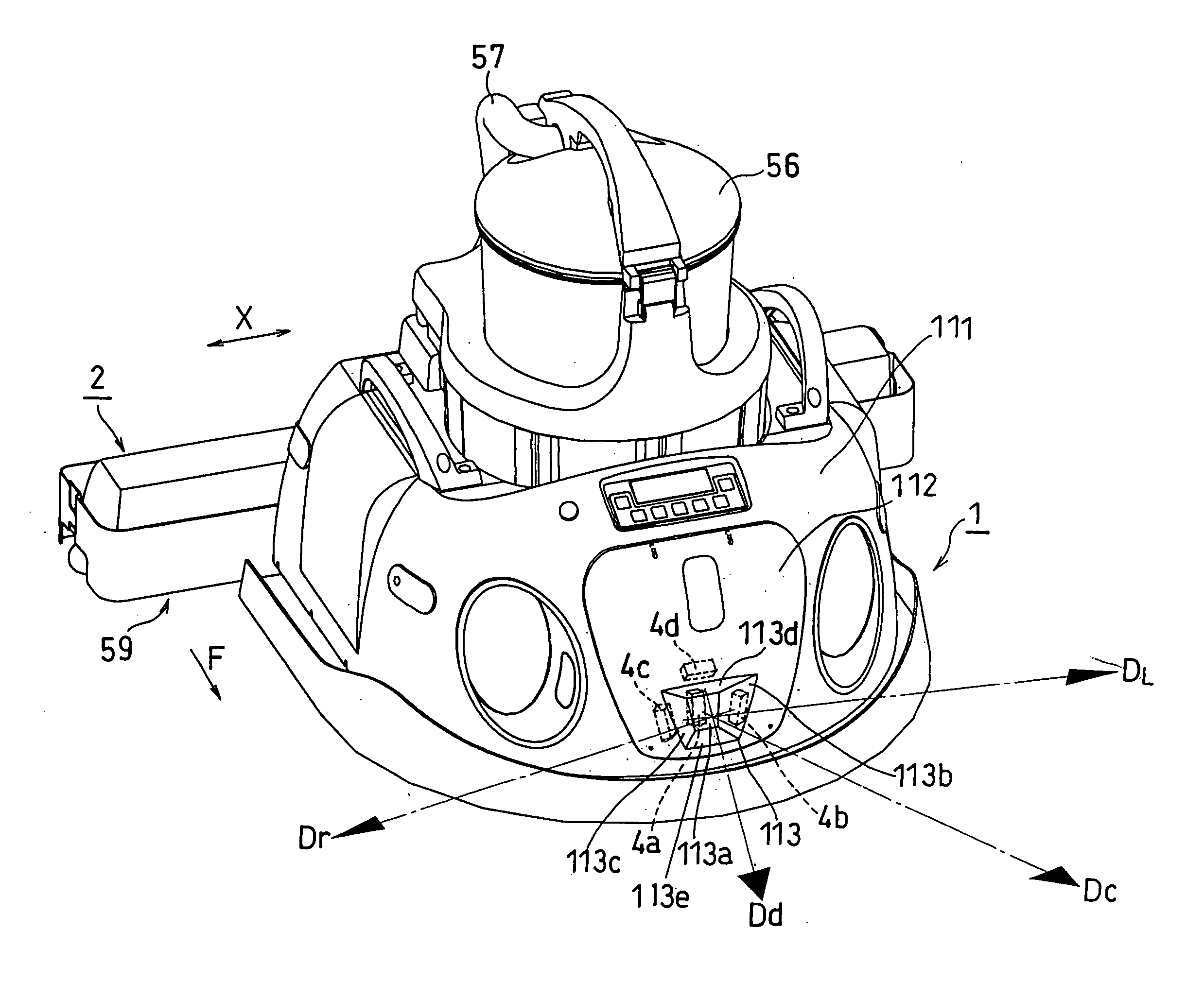
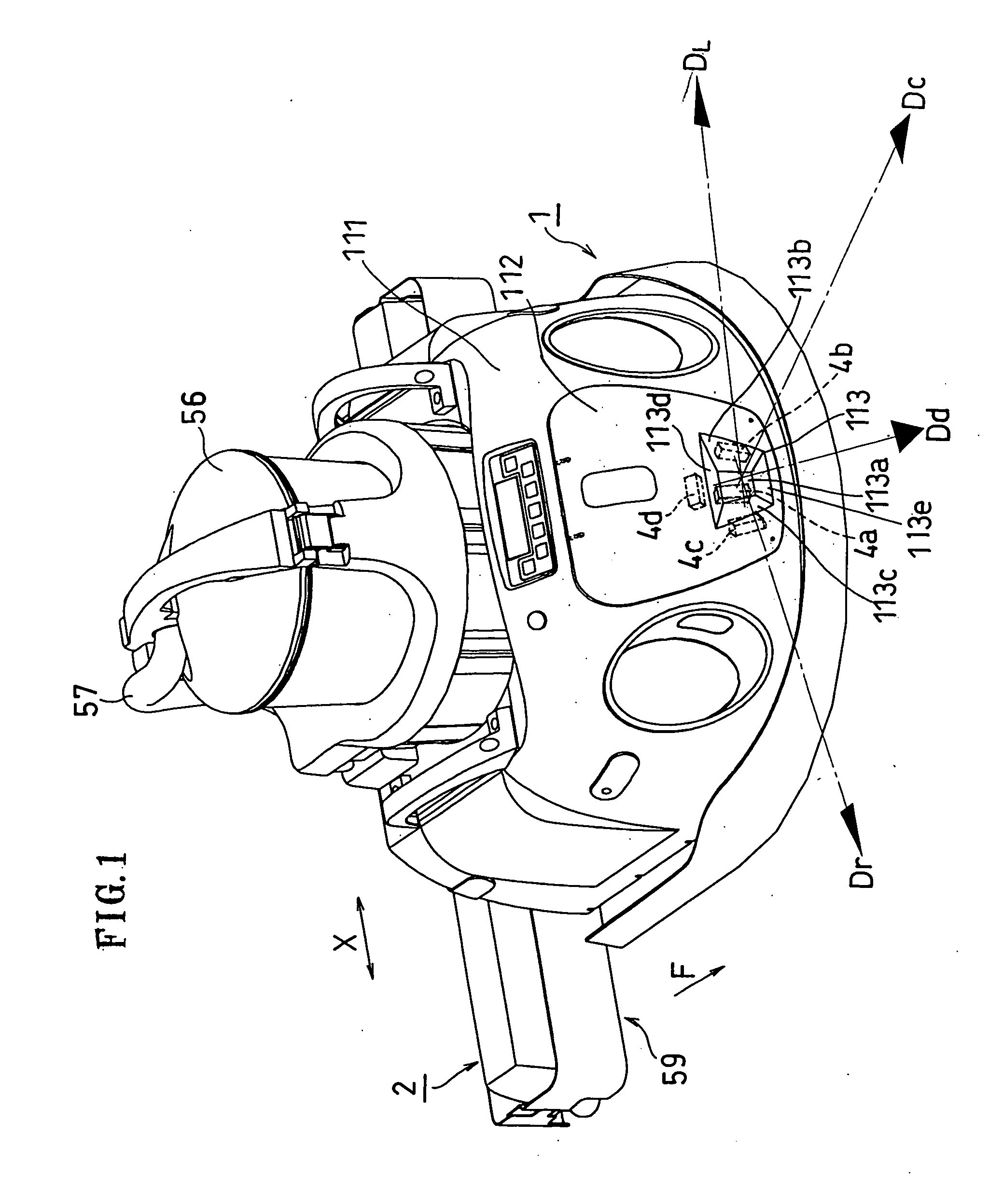
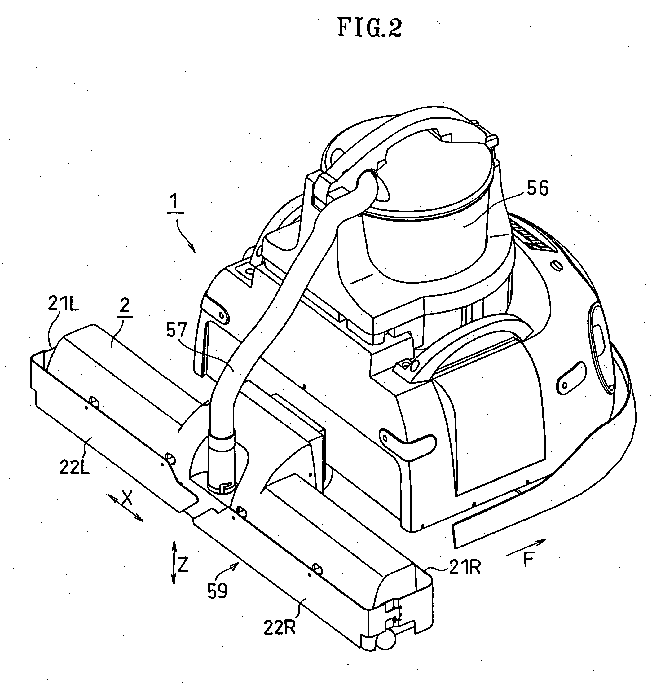
[0122] As shown in FIGS. 1 and 2, the self-propelled working robot of the present embodiment includes a carriage-like traveling assembly 1 for self-traveling across the floor surface, and a working assembly 2 for sucking up dust from the floor. The working assembly 2 is provided behind the traveling assembly 1 with respect to the primary moving direction F of the traveling assembly 1.

[0123] The suction unit 56 is provided in an upper portion of the traveling assembly 1. The suction unit 56 includes a dust receptacle (tank), a blower motor, a filter, etc. The suction unit 56 and the working assembly 2 are connected to each other via a suction hose 57. A suction hole 59 is provided on the lower surface of the working assembly 2. As the present working robot does cleaning work while traveling around, the dust particles on the floor are sucked up through the suction hole 59 one after another, thereby cleaning the floor surface.

[0124] Traveling Assembly 1:

[0125] As shown in FIG....

second embodiment

[0246]

[0247] General Configuration:

[0248] A working robot 100 of this embodiment includes the traveling assembly 1 and the working assembly 2 as shown in FIGS. 15(a) and 15(b). As shown in FIGS. 14(a) and 14(b), the traveling assembly 1 includes the driven wheels 6a and 6b for driving the traveling assembly 1, and non-driven wheels 9a and 9b for maintaining the balance of the traveling assembly 1. The driven wheels 6a and 6b are driven by drive motors 5a and 5b, respectively. The drive motors 5a and 5b can be spun in opposite directions (reversible), and the spinning thereof is controlled by a microcomputer (control means) 8.

[0249] When traveling straight, the two drive motors 5a and 5b are spun in the same direction so that the traveling assembly 1 can move forward or backward.

[0250] For a turn (rotating) operation, the two drive motors 5a and 5b are spun in opposite directions, whereby the traveling assembly 1 can turn (rotate) in place about a vertical line (center of rotation...


PUM


Abstract

The present invention relates to a self-propelled working robot, including a first distance sensor 4a and a second distance sensor 4b (4c) for measuring the distance to an obstacle W in front of the robot. The robot includes first determination means for comparing a first measured distance Dc to the obstacle obtained by the first distance sensor 4a with a predetermined first threshold value to determine the proximity to the obstacle W, second determination means for comparing a second measured distance Dr (DL) to the obstacle W obtained by the second distance sensor 4b (4c) with a predetermined second threshold value to determine the proximity to the obstacle, and changing means for changing the first or second threshold value based on information regarding an inclination angle of the obstacle W obtained from the first and second measured distances.

Description

TECHNICAL FIELD [0001] The present invention relates to a working robot suitable for doing work on a floor surface near a wall, or the like. BACKGROUND ART [0002] There are known self-propelled working robots in the prior art for doing work such as cleaning the floor surface near the wall. [0003] A working robot of this type includes a plurality of distance sensors for measuring the distance from the robot body to an obstacle. If the distance measured by the distance sensor is smaller than a predetermined threshold value, the robot is controlled so as not to collide with the wall by a predetermined avoidance operation. The threshold value is set to a predetermined constant value such that the robot will not be too far away from the wall. [0004] Where the threshold value is not sufficiently large, however, if the inclination angle between the body and the obstacle, a side portion of the front end portion of the robot comes proximate to the obstacle even though the central head portio...

Claims


Application Information

Patent Timeline
IPC IPC(8): G06F19/00G05D1/02
CPCG05D1/0219G05D1/0227G05D2201/0203G05D1/0255G05D1/0238
Inventor KAWAGOE, NOBUKAZUOYOKOTA, SHIEGERU
Owner FIGLA
Why Eureka
Try Eureka