Vehicle driving assist system

a technology for driving assist and vehicles, applied in the direction of process control, pedestrian/occupant safety arrangement, instruments, etc., can solve the problem of difficulty for drivers to keep track of the individual operating state of the vehicle driving assist system

Inactive Publication Date: 2007-02-08
NISSAN MOTOR CO LTD
View PDF12 Cites 49 Cited by
  • Summary
  • Abstract
  • Description
  • Claims
  • Application Information

AI Technical Summary

Benefits of technology

[0006] The vehicle driving assist system disclosed in Japanese Laid-Open Patent Publication No. 2005-112243 informs the driver that the possibility of the host vehicle colliding with the preceding obstacle is high by causing pulsed reaction forces to be exerted by the accelerator pedal and the brake pedal. In recent years, vehicles are provided with a variety of driving assist systems for controlling the behavior of the host vehicle. When two or more driving assist systems are used in a vehicle, it may be difficult for some drivers to keep track of the individual operating states of these vehicle driving assist systems. Consequently, it is beneficial for the driver to be informed of the operating states of the systems installed in the host vehicle in a manner that can be readily understood by the driver.
[0007] In accordance with one aspect of the present invention, a vehicle driving assist system is provided that basically comprises a traveling situation detecting section, a risk potential calculating section, an actuation reaction force control section, a vehicle behavior control section and a behavior control operating state notifyin

Problems solved by technology

When two or more driving assist systems are used in a vehicle, it may be difficult for some dr

Method used


Image

  • Vehicle driving assist system
  • Vehicle driving assist system
  • Vehicle driving assist system

Examples


first embodiment

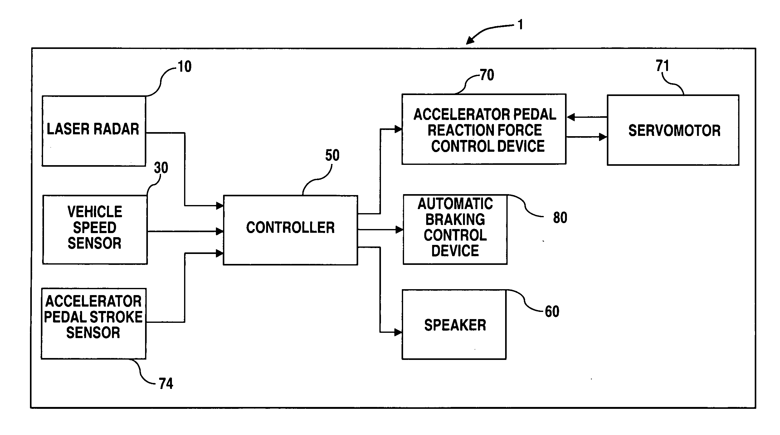
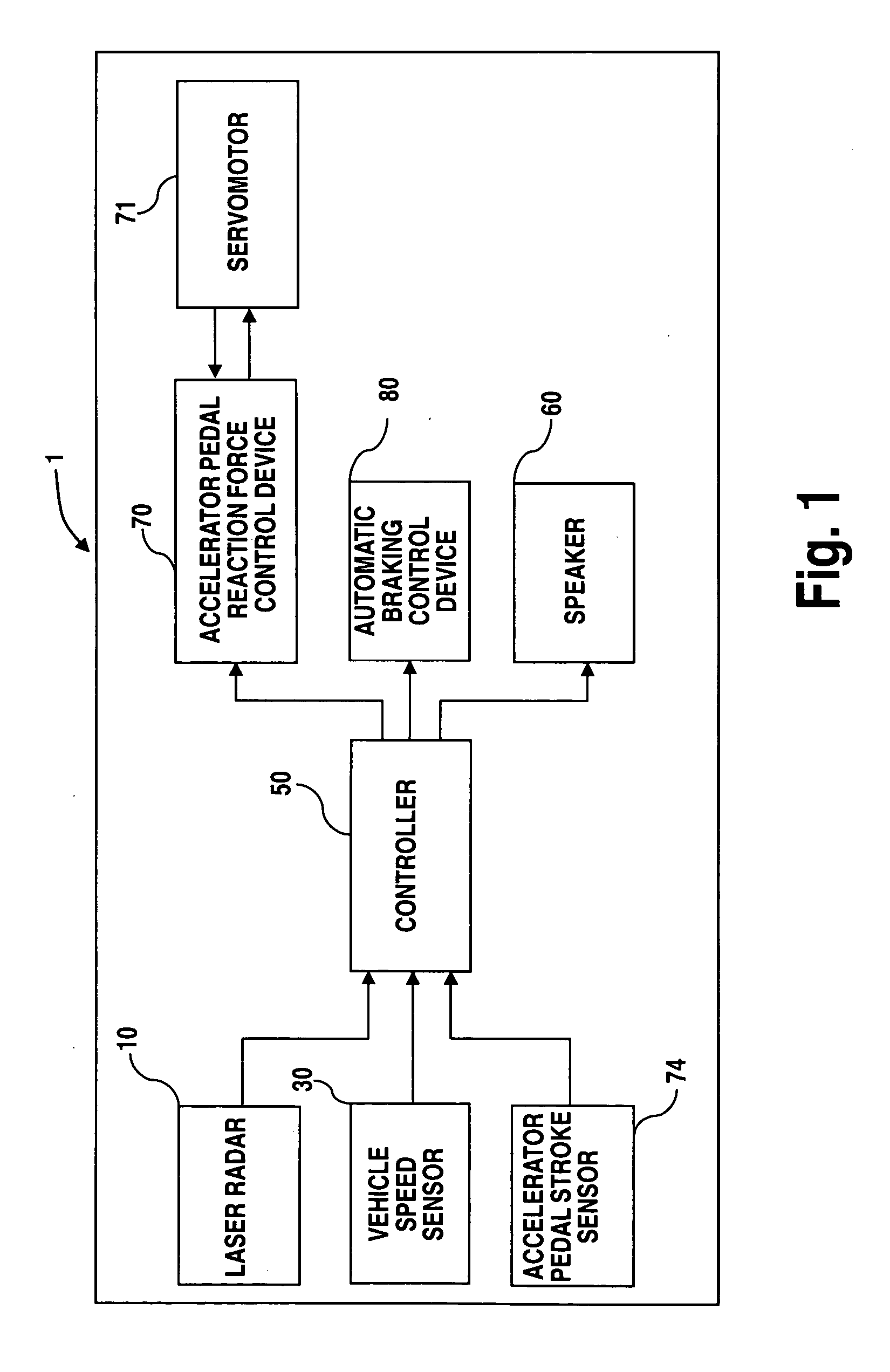
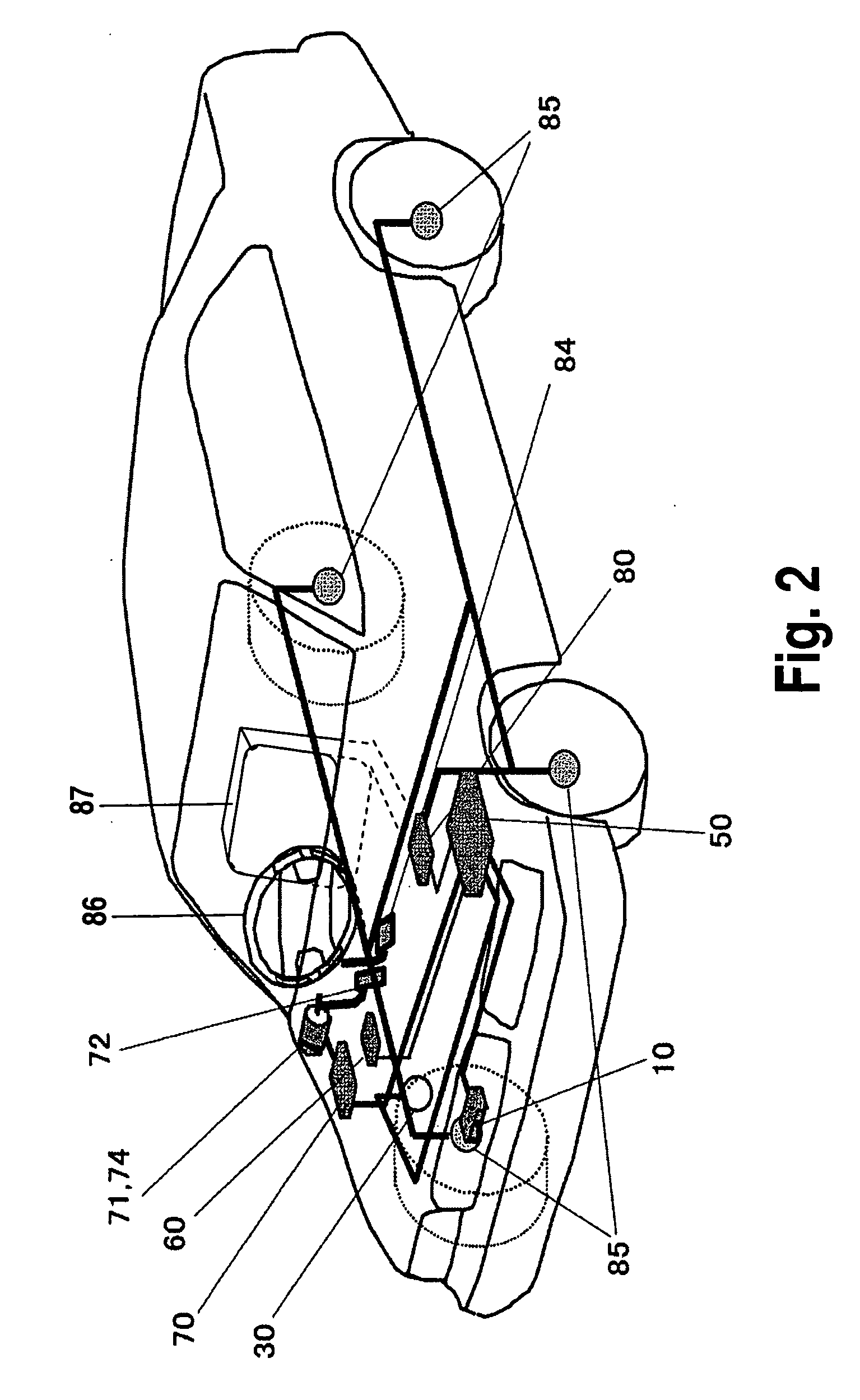
[0041] Referring initially to FIG. 1, a vehicle driving assist system is illustrated in accordance with a first embodiment of the present invention. FIG. 1 is a block diagram of a vehicle driving assist system in accordance with the first embodiment of the present invention. FIG. 2 is a schematic perspective view of a vehicle (hereinafter also called “the host vehicle”) in which the vehicle driving assist system shown in FIG. 1 is installed in accordance with the first embodiment of the present invention.

[0042] First, the main structures and features of the vehicle driving assist system will now be explained. A laser radar 10 is mounted to a front grill portion, a bumper portion, or the like of the host vehicle and serves to horizontally scan a region in front of the host vehicle with an infrared light pulse. The laser radar 10 then measures the reflected light resulting from the infrared light reflecting off of a plurality of reflecting objects located in front of the host vehicle...

second embodiment

[0103] A vehicle driving assist system in accordance with a second embodiment of the present invention will now be explained. FIG. 17 is a system diagram of the vehicle driving assist system 2 in accordance with the second embodiment. In FIG. 17, parts having the same functions as the parts of the first embodiment shown in FIGS. 1 and 2 are indicated with the same reference numerals. The second embodiment will be explained chiefly by describing its differences with respect to the first embodiment.

[0104] As shown in FIG. 17, the vehicle driving assist system 2 in accordance with the second embodiment has a collision speed reducing device or intelligent brake assist (IBA) device 90 instead of an automatic deceleration control device 80. The intelligent brake assist device 90 is configured to operate in situations where the host vehicle is following a preceding vehicle and the system determines that the host vehicle is at risk of contacting the preceding vehicle or that it is necessar...

third embodiment

[0122] A vehicle driving assist system in accordance with a third embodiment of the present invention will now be explained. FIG. 23 is a system diagram of the vehicle driving assist system 3 in accordance with the third embodiment. In FIG. 23, parts having the same functions as the parts of the first embodiment shown in FIGS. 1 and 2 are indicated with the same reference numerals. The third embodiment will be explained chiefly by describing its differences with respect to the first embodiment.

[0123] As shown in FIG. 23, the vehicle driving assist system 3 in accordance with the third embodiment has a lane departure preventing (LDP) device 100 instead of an automatic deceleration control device 80. The lane departure preventing device 100 executes a lane departure prevention control contrived to prevent lane departure when there is the possibility that the host vehicle in which the system 3 is installed will depart from the lane in which it is traveling. The lane departure preventi...


PUM


Abstract

A vehicle driving assist system is configured to provide a driver with advanced notification regarding changes in the operating states of the controls when several controls are being executed. The vehicle driving assist system has a controller configured to execute an accelerator pedal actuation reaction force control based on a risk potential that indicates a degree of convergence between the host vehicle and a preceding obstacle and an automatic braking control based on the possibility of contact between the host vehicle and the preceding obstacle. When the automatic braking control will change from a low operating state to a high operating state while an actuation reaction force is being generated in the accelerator pedal in accordance with the risk potential, a pulsed supplemental reaction force is generated in the accelerator pedal and an alarm sound is generated.

Description

CROSS-REFERENCE TO RELATED APPLICATIONS [0001] This application claims priority under 35 U.S.C. § 119 to Japanese Patent Application No. 2005-228494. The entire disclosure of Japanese Patent Application No. 2005-228494 is hereby incorporated herein by reference.BACKGROUND OF THE INVENTION [0002] 1. Field of the Invention [0003] The present invention relates to a vehicle driving assist system configured to assist a driver with respect to the operation of a vehicle. [0004] 2. Background Information [0005] One example of a vehicle driving assist system is disclosed in Japanese Laid-Open Patent Publication No. 2005-112243. In this publication, the vehicle driving assist system controls the actuation reaction forces exerted by the accelerator pedal and the brake pedal of a vehicle when those pedals are operated based on the risk potential in an area surrounding the host vehicle and increases the braking force exerted against the host vehicle when the possibility that the host vehicle wil...

Claims


Application Information

Patent Timeline
IPC IPC(8): G06F7/00B60K26/04B60R21/00B60T7/12B60W30/00B60W30/09B60W50/14B60W50/16G08G1/16
CPCB60W50/16B60K26/021
Inventor KONDOH, TAKAYUKIMATSUSHITA, YASUHIRO
Owner NISSAN MOTOR CO LTD
Why Eureka
Try Eureka