Self-calibrating sensor

a self-calibrating, sensor technology, applied in the direction of speed/acceleration/shock measurement, liquid/fluent solid measurement, instruments, etc., can solve the problems of increasing sensor manufacturing costs and time, and the technique is both costly and complicated to implement in each individual sensor

Inactive Publication Date: 2007-02-08
HONEYWELL INT INC
View PDF19 Cites 34 Cited by
  • Summary
  • Abstract
  • Description
  • Claims
  • Application Information

AI Technical Summary

Benefits of technology

[0010] It is a further aspect of the embodiments to provide for a low cost self-calibrating sensor.
[0013] In one aspect, a system for self-calibrating a sensor has a calibration circuit which compares an output signal of the sensor with a predetermined reference signal associated with a reference property and increments or decrements the sensor operating bias according to the deviation between the predetermined reference signal and sensor output signal such that the sensor output corresponds to the predetermined reference voltage. Advantageously, the calibration circuit can be implemented using low-cost circuit designs without providing circuitry for performing complex algorithms for sensor characterization, such as those for calculating calibration coefficients and transfer functions. Furthermore, the calibration circuit can be conveniently embedded in the sensor.
[0016] In use, the biasing controller, in response to receiving a control signal from the differential circuitry, can increment or decrement the operating bias point of the sensor according to the deviation to substantially eliminate the deviation between the predetermined reference signal and the sensor output signal such that the sensor output signal corresponds to the predetermined reference signal.
[0019] When the self-calibrating sensor is operating in calibration mode, the biasing controller, in response to receiving a control signal from the differential circuitry, can increment or decrement the operating bias point of the sensor to substantially eliminate the deviation between the predetermined reference signal and the sensor output signal such that the sensor output signal is similar or equal to the predetermined reference signal. In normal mode, the sensing device can operate at the calibrated operating bias point.

Problems solved by technology

Such production requirements therefore lead to increase in sensor manufacturing costs and time.
Such a technique is both costly and complicated to implement in each individual sensor.

Method used


Image

  • Self-calibrating sensor
  • Self-calibrating sensor
  • Self-calibrating sensor

Examples


Embodiment Construction

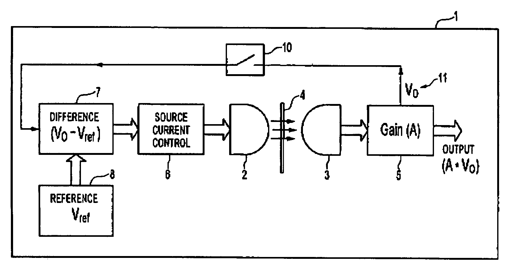
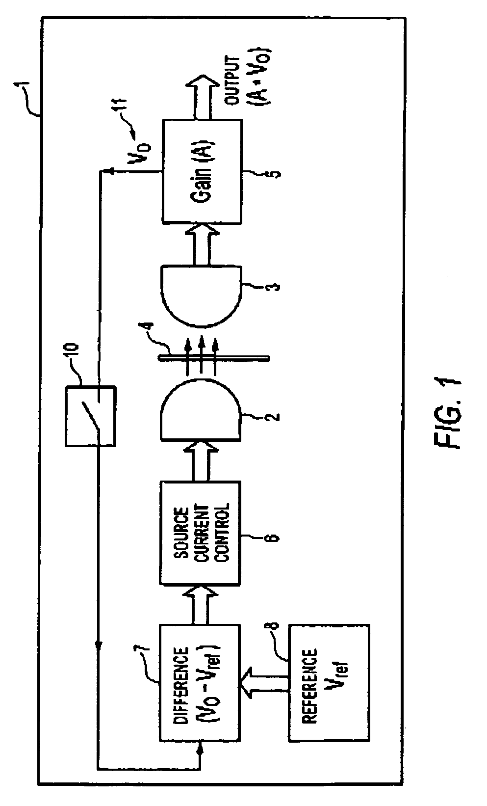
[0031] Referring to FIG. 1 of the accompanying drawings, which illustrates a block diagram of a self-calibrating sensor according to a preferred embodiment, the principle elements of the self-calibrating sensor 1 include a sensor transducer 2, 3, an amplifier 5, coupled to the output of the sensor transducer 3, and a self-calibrating circuit 6, 7, 10 coupled thereto for providing self-calibration of the sensor. An IR source 2, such as an IR LED and an associated photodetector 3, such as a phototransistor, form the sensor transducer. The self calibrating system has a differential circuitry 7, a biasing controller / source 6, coupled to the output of the differential circuitry 7 and the input of the sensor transducer 2, and a calibration switch 10 interposing an output of the sensor transducer and the input of the differential circuitry 7.

[0032] The illustrative embodiment depicted in FIG. 1 provides a general approach to providing a self-calibration sensor which can perform self-calib...


PUM


Abstract

A method for self-calibrating a sensor can be implemented in a system having a calibration circuit. The calibration circuit has differential circuitry which compares an output signal of the sensor with a predetermined reference signal associated with a reference property. A bias controller increments or decrements the sensor operating bias according to the deviation between the predetermined reference signals and sensor output signal such that the sensor output corresponds to the predetermined reference voltage. The calibration circuit can be embedded in the sensor to provide a self-calibrating sensor. Logic circuitry can be used to form the calibration circuit.

Description

TECHNICAL FIELD [0001] Embodiments relate to sensor calibration and, more particularly, to systems and methods of self-calibrating sensors. Embodiments also relate to self-calibrating sensors, such as, infra-red (IR), Hall-Effect, Magneto-Resistive and piezo-resistive pressure self-calibrating sensors. BACKGROUND OF THE INVENTION [0002] Sensors are employed in a whole range of technological applications including automotive, medical and printing applications to name a few. Such applications require sensors which can operate reliably and reproducible according to specified performance characteristics. For this reason, sensors are normally individually calibrated during production to offset minor deviations in sensor performance resulting from mass production techniques ensuring that measurements can be performed accurately for each and every sensor produced. [0003] Performance of an electronic sensor is dependent on the transducer / material properties and the biasing current or voltag...

Claims


Application Information

Patent Timeline
Patent Type & Authority Applications(United States)
IPC IPC(8): G01D18/00G01R35/00
CPCG01D18/008
Inventor MUNIRAJU, RAGHAVENDRAVEEDU, SUDHEER PULIKKARABLACKSTONE, JAMES L.
Owner HONEYWELL INT INC
Why Eureka
Try Eureka