
Flexible segment fishing pole

a flexible segment and fishing rod technology, applied in the field of fishing poles, can solve the problems of unification, increased fishing rod flexibility, and long time in water, and achieve the effects of reducing fishing rod flexibility, increasing rod flexibility, and increasing fishing rod flexibility

Inactive Publication Date: 2007-02-15
JUNG MAN YOUNG
View PDF9 Cites 9 Cited by
  • Summary
  • Abstract
  • Description
  • Claims
  • Application Information

AI Technical Summary

Benefits of technology

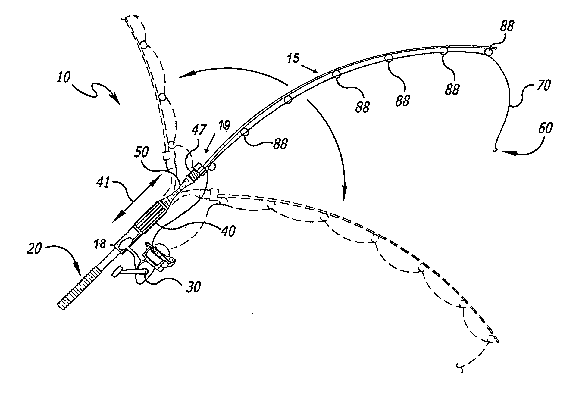
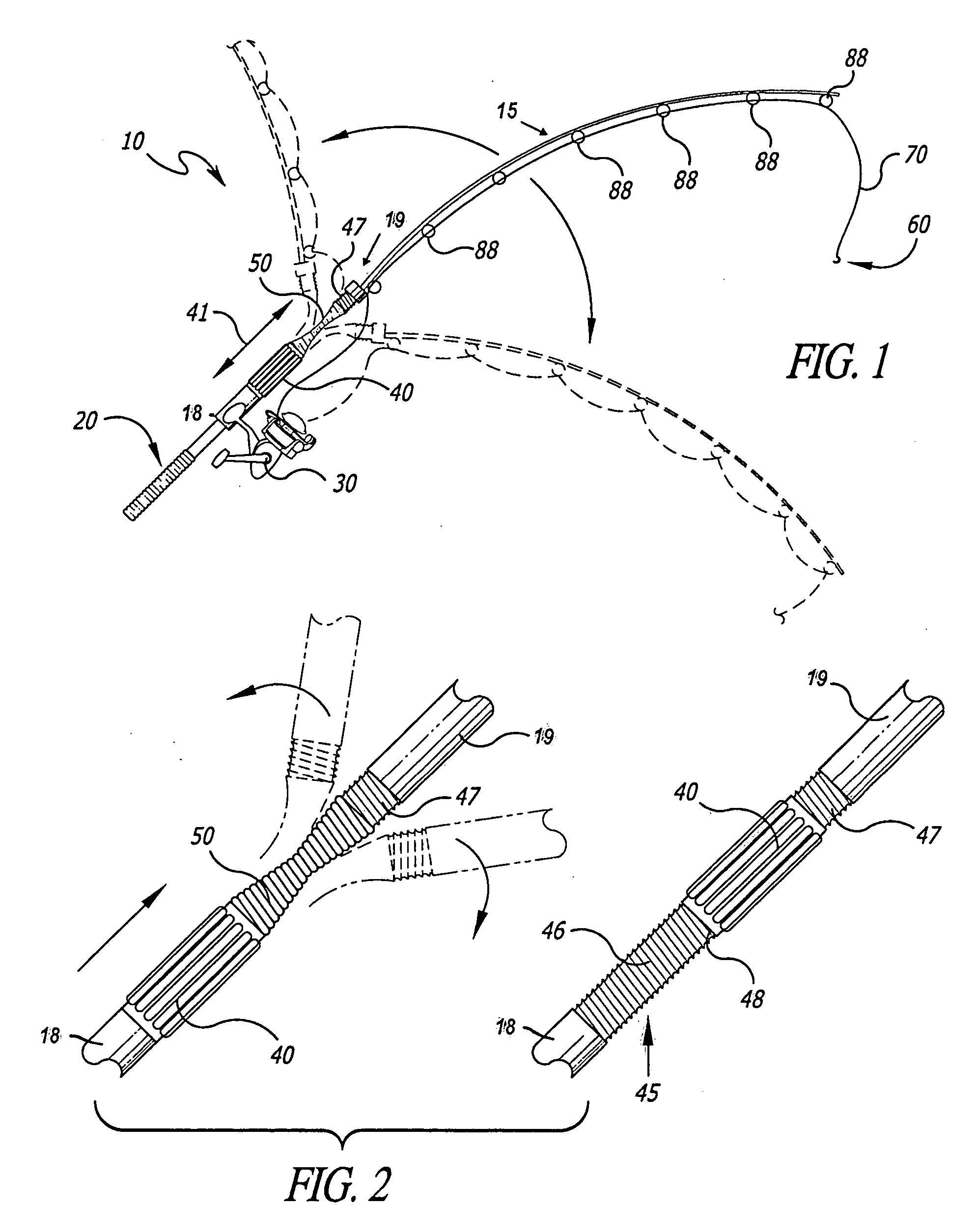
[0018] In use, the user sets the sleeve in the disengaged position and casts the lure. The user may utilize the greater flexibility of the fishing rod to cast the lure a greater distance than he could without the increased flexibility of the rod, either by casting overhead or sideways. Once the lure has been cast, the user then positions the sleeve into the engaged position, greatly reducing the flexibility of the fishing rod and making it more suitable for use in setting a hook during a fish strike at the lure and then reeling in the catch. As needed, the user may choose to set the sleeve in its semi-engagement position to control an undesirable event of excessive vibrations depending on the degree of a rod's own flexing characteristics.
[0019] Thus, the present invention may be easily retrofitted onto an existing fishing pole, or integrated into the manufacture of a new fishing pole. The present invention provides the user with a choice between greater pole flexibility, which is useful to cast a lure a relatively great distance, and conventional pole flexibility for a user to select after casting. The device is easy to use and easy to maintain. The present device is, moreover, relatively inexpensive to manufacture, and does not include complicated pulleys or excessive mechanisms that can be difficult to use and maintain. Other features and advantages of the present invention will become apparent from the following more detailed description, taken in conjunction with the accompanying drawings, which illustrate, by way of example, the principles of the invention.

Problems solved by technology

A longer cast results in a longer time in the water for the fishing lure, per cast, thereby increasing the odds that a fish will be attracted to the lure and will bite.
No technical literature has been found about unifying an angular mop section to facilitate surface cleaning and a flexing rod section for improved projection of fish line.
But there is offered no hint of how to regulate the flexibility of the long spring rod once it is fixed to the handle.
Such deformation may not be universally applied to different blank rods available or adds a costly process that might be saved otherwise.
The spring is limited to make linear flexing movements in the frame of yoke requiring a separate adjusting knob adding to the complexity and weight to the rod contrary to the desirable free and sensitive flexes before and after fish bites.
Because a spring is made of hard material like metal whipping motion during bait casting with the spring-rod will be too heavy for a sensitive bait control and may result in unsafe casting actions.
Such a device has a complicated set of pulleys and cabling, and as such is both somewhat difficult to use and maintain, and is considerably longer than an average fishing pole.
Further, such a device is awkward to use due to its extended length.

Method used


Image

  • Flexible segment fishing pole
  • Flexible segment fishing pole
  • Flexible segment fishing pole

Examples


third embodiment

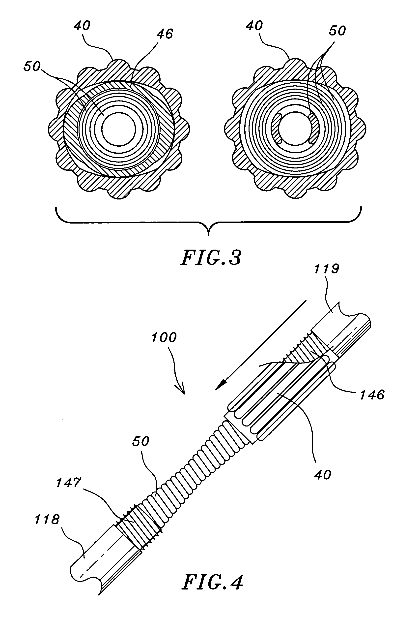
[0040] In the slotted model according to the invention illustrated in FIG. 5, a fishing rod 200 comprises a lower rod portion 218 terminating with an elongated boss 228, which has a tip portion coaxially press fitted into the flexible segment 50. A cylindrical sleeve 240 is mounted slidably over the segment 50 as well as boss 228. The opposite end of the flexible segment 50 is fitted with an upper rod portion 219 also firmly attached in line with the lower rod portion 218. The sleeve 240 has two serial slots 242 and 244 that open to the opposite ends to engage pins or protrusions 246 and 247 mounted on the lower and upper rod portions 218 and 219, respectively. The upper slot 244 is shorter than the lower slot 242, which extends to the middle of the sleeve 240. In order to give the sleeve 240 positive shifts between engagement and disengaged positions and a midway position, the longer slot 242 has two short circumferential notches, one at 245 near the lower end of sleeve 240 and the...

fourth embodiment

[0044]FIG. 6 illustrates the present invention wherein a fishing rod 300 comprises a lower rod portion 318 made of a hollow blank rod to which a handle is attached at its lower end. The top end of the lower portion 318 is provided with a boss 346 of reduced diameter for insertion into an open end of the flexible segment 50. In order to form a positive abutment against the spring 50, the boss 346 of lower portion 318 may be threaded externally conforming to the helical extensions of the coil spring. An upper rod portion 319 is similarly provided with a lower boss 347 inserted threadedly into the other end of the spring 50 thereby providing two prominent flexing points as at 351 and 352 along the spring 50. Also, as an alternative method to reinforce the flexible segment 50, a rigid rod or latch 340 that slides between an engagement position that rigidly connects the upper rod portion 319 with the lower rod portion 318, and a disengaged position where the latch 340 is cleared from a r...


PUM


Abstract

An improvement to a fishing pole is disclosed, the improvement including a multi-flex segment that separates a resilient rod of the fishing pole into lower and upper portions. Both the upper and lower portions are interconnected through the multi-flex segment. A rigid retractable sleeve is positionable in either a disengaged position away from the multi-flex segment or in an engaged position over the multi-flex segment. In the disengaged position, the sleeve is positioned so that it covers part of the lower section of the rod, but none of the multi-flex segment, thereby allowing the multi-flex segment to flex more freely during casting, for example. In its engaged position, however, the sleeve is positioned to cover the multi-flex segment completely, interconnecting in a rigid fashion the upper portion of the rod to the lower portion of the rod.

Description

CROSS REFERENCE TO RELATED APPLICATION [0001] This application is a continuation-in-part application of Jung, Man U.S. application Ser. No. 10 / 985,675 filed Nov. 11, 2004 entitled Flexible Segment Fishing Pole.FIELD OF THE INVENTION [0002] The present invention relates generally to fishing poles, and, more particularly, is directed towards a fishing pole with flexible segment for greater casting distances. DISCUSSION OF RELATED ART [0003] Prior art fishing poles have been developed to increase the distance that a fisherman can cast a fishing lure. A longer cast results in a longer time in the water for the fishing lure, per cast, thereby increasing the odds that a fish will be attracted to the lure and will bite. Moreover, a longer cast results in less competition for fish in waters where other fisherman cannot cast, thereby increasing the odds that a fisherman who can cast a greater distance will catch fish. Indeed, certain larger fish prefer deeper waters, and therefore the fisher...

Claims


Application Information

Patent Timeline
Patent Type & Authority Applications(United States)
IPC IPC(8): A01K87/02A01K87/00
CPCA01K91/02A01K87/02
Inventor JUNG, MAN YOUNG
Owner JUNG MAN YOUNG
Learn More