Ultrasonic flow sensor

a technology of ultrasonic flow sensor and flow sensor, which is applied in the direction of volume/mass flow measurement, measurement devices, instruments, etc., can solve the problems of difficult to measure very small flow-induced upstream to downstream time differences, and the inability to reliably get ultrasonic energy into and out of fluid flowing in ultrasonic flow sensor, etc., to achieve the effect of reducing the risk of leakage, and reducing the cost of operation

Inactive Publication Date: 2007-02-15
BROOKS INSTRUMENT
View PDF52 Cites 57 Cited by
  • Summary
  • Abstract
  • Description
  • Claims
  • Application Information

AI Technical Summary

Problems solved by technology

Although the technology described in the co-pending application provides many advantages over conventional ultrasonic flow measurement systems and signal processing techniques, reliably getting ultrasonic energy into and out of fluid flowing in an ultrasonic flow sensor continues to be a difficult problem.
Further, it is often difficult to measure very small flow-induced upstream to downstream time differences, particularly at relatively low rates, such as, for example, between 5 and 50 ml / min (and consequently relatively small internal sensor conduit diameters).
Still further, where the acoustic impedance of the material from which the sensor conduit is formed is relatively closely matched by the acoustic impedance of the fluid flowing therein, one typically cannot rely on the acoustic energy imparted to the fluid being internally reflected by the material of the sensor conduit.

Method used


Image

  • Ultrasonic flow sensor
  • Ultrasonic flow sensor
  • Ultrasonic flow sensor

Examples


Embodiment Construction

[0029] This invention is not limited in its application to the details of construction and the arrangement of components set forth in the following description or illustrated in the drawings. The invention is capable of other embodiments and of being practiced or of being carried out in various ways. Also, the phraseology and terminology used herein is for the purpose of description and should not be regarded as limiting. The use of “including,”“comprising,” or “having,”“containing,”“involving,” and variations thereof herein, is meant to encompass the items listed thereafter and equivalents thereof as well as additional items.

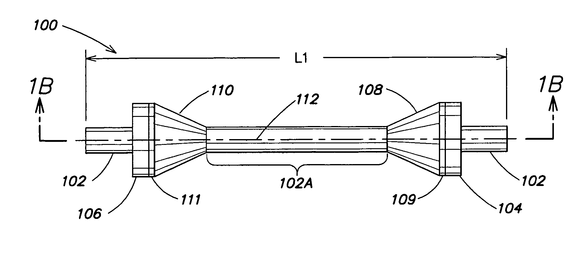
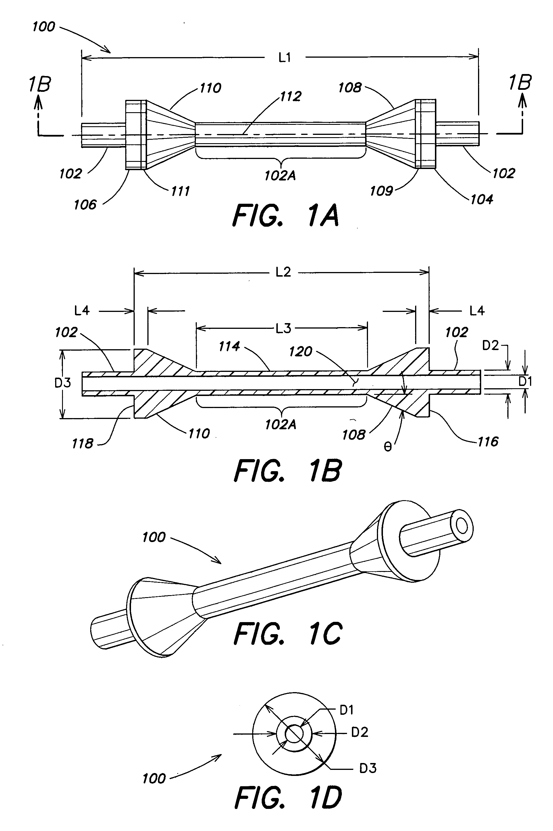
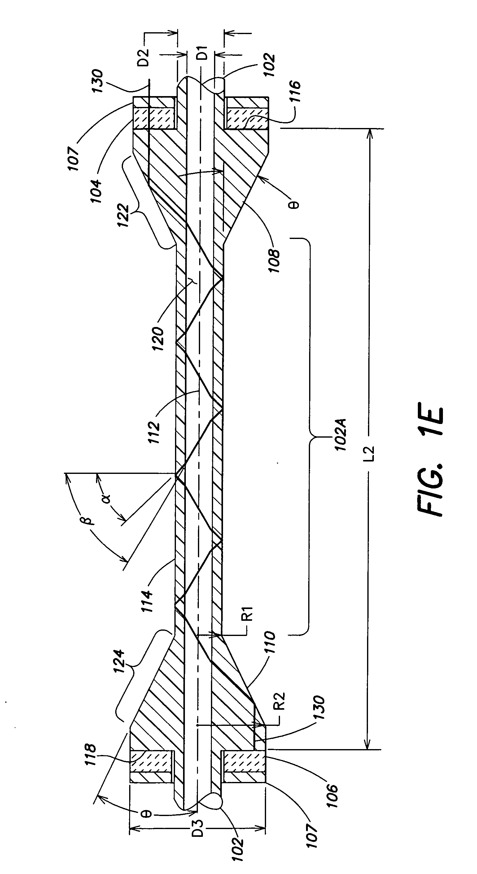
[0030] FIGS. 1A-E illustrate an ultrasonic fluid flow sensor in accordance with one embodiment of the present invention. As illustrated in FIG. 1A, the flow sensor 100 includes a conduit 102, a first ultrasonic transducer 104 disposed at a first location along a length of the conduit 102, and a second ultrasonic transducer 106 disposed at a second location alo...


PUM


Abstract

An ultrasonic flow sensor that includes a conduit having a length, a first ultrasonic transducer disposed at a first position along the length of the conduit, a second ultrasonic transducer disposed at a second position along the length of the conduit, the second position being spaced apart from the first position, a first reflecting interface and a second reflecting interface. The first reflecting interface is in registration with the first ultrasonic transducer to receive first acoustic energy from the first ultrasonic transducer and to reflect the first acoustic energy in a direction generally along a length of the conduit and into a fluid within the conduit. The second reflecting interface is in registration with the second ultrasonic transducer to receive second acoustic energy from the second ultrasonic transducer and to reflect the second acoustic energy in a direction generally along the length of the conduit and into the fluid within the conduit.

Description

BACKGROUND [0001] 1. Field of Invention [0002] The present invention relates to ultrasonic flow measurement and more particularly to an improved ultrasonic flow sensor that may be used alone or as part of a flow controller. [0003] 2. Discussion of Related Art [0004] Ultrasonic flow sensing is often employed where a non-invasive approach to sensing fluid flow in a conduit is desired. Typical applications for flow sensors include, for example, the manufacture and / or processing of semiconductors. [0005] Traditionally, a pair of ultrasonic transducers is employed where an upstream ultrasonic transducer transmits ultrasonic waves that are received by a downstream ultrasonic transducer, and the downstream ultrasonic transducer transmits ultrasonic waves that are received by the upstream ultrasonic transducer. The difference between the time of flight of the upstream ultrasonic wave and the time of flight of the downstream ultrasonic wave is determined and the velocity of the fluid flowing...

Claims


Application Information

Patent Timeline
Patent Type & Authority Applications(United States)
IPC IPC(8): G01F1/66
CPCG01F1/662
Inventor MAGINNIS, THOMAS OWENVU, KIM NGOC
Owner BROOKS INSTRUMENT
Why Eureka
Try Eureka