Hidden electric power elevating stand structure

a technology of electric power and hidden electric power, which is applied in the field of hidden electric power elevating stand structure, can solve the problems of not being able to fully adjust the horizontal attachment with the ceiling, not being able to fully adjust the horizontal attachment, and not being able to install the elevating stand easily, so as to facilitate its installation and maintenance, and beautify the overall external appearan

Inactive Publication Date: 2007-02-15
LO WEN PING
View PDF12 Cites 59 Cited by
  • Summary
  • Abstract
  • Description
  • Claims
  • Application Information

AI Technical Summary

Benefits of technology

[0008] It is a primary objective of the present invention to provide an improved hidden electric power elevating stand structure, so that the elevating stand can have an easier installation, a smoother transmission, and an adjustable angle of elevation.
[0009] The foregoing elevating stand structure comprises upper and lower frame bodies, upper and lower braking rod crossed with each other and installed longitudinally on the lateral sides of the upper and lower frame bodies; wherein a transversal rod is disposed at the intersection of the bottom of the lower braking rod and the upper braking rod for connecting an electric power screw rod, such that the transversal rod of the lower braking rod is sheathed into a track disposed between two longitudinal sides of the lower frame body, and the extension or withdrawal of the screw rod drive the frame body to ascend or descend respectively. Since the screw rod is moved according to the braking rod to have a consistent pushing force, such arrangement can achieve the long arm moment and power saving effects.
[0010] The foregoing elevating stand structure includes dual bearings installed between both ends of the transversal rod at the bottom of the lower braking rod, so that the bearing is situated in the track of the lower frame body to make the braking rods to slide freely and smoothly, so as to prevent the braking rods from being shifted.
[0012] The foregoing elevating stand structure installs a fixing stand, and the fixing stand has a long hole. The fixing stand is installed onto the ceiling, and then the elevating stand is installed onto the fixing stand. Such arrangement facilitates its installation and maintenance, and the long hole constitutes the adjustment of the angle of elevation.
[0013] The foregoing elevating stand structure installs a plurality of sockets and electric connectors at the lower frame body for connecting an external power supply or a control device in a hidden manner, so as to beautify the overall external look.

Problems solved by technology

In general, the traditional stand for placing a videoconferencing or audio / video equipment such as an overhead projector, a speaker and an optical disk drive is not adjustable regardless of being fixed at a certain height or suspended from a ceiling.
It is not easy to install the elevating stand.
Since the ceiling is often not level, and the overall structure is quite heavy (over 25 kg), therefore it requires at least three construction workers to adjust the stand.
Furthermore, it is unable to fully adjust the horizontal attachment with the ceiling, which may be dangerous to the construction worker to carry out such aerial operation.
It is difficult to maintain or repair the elevating stand, since the control circuit and receiver of the remote control are installed inside the elevating stand.
If the circuit breaks down and the circuit is in a close circuit, then the maintenance person cannot remove the circuit by itself, but have to remove the whole set for maintenance.
The motor consumes much electric power.

Method used


Image

  • Hidden electric power elevating stand structure
  • Hidden electric power elevating stand structure
  • Hidden electric power elevating stand structure

Examples


Embodiment Construction

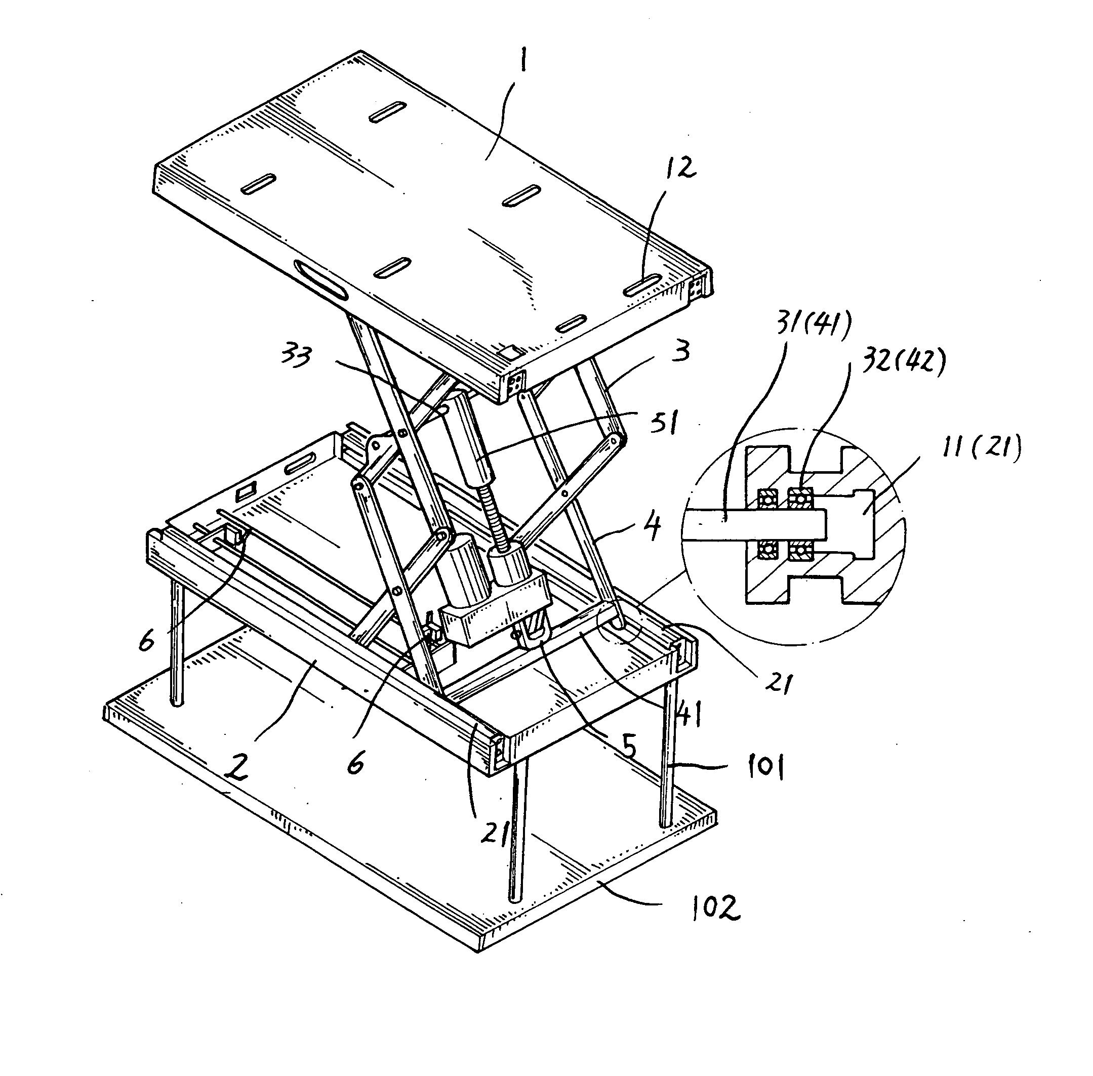
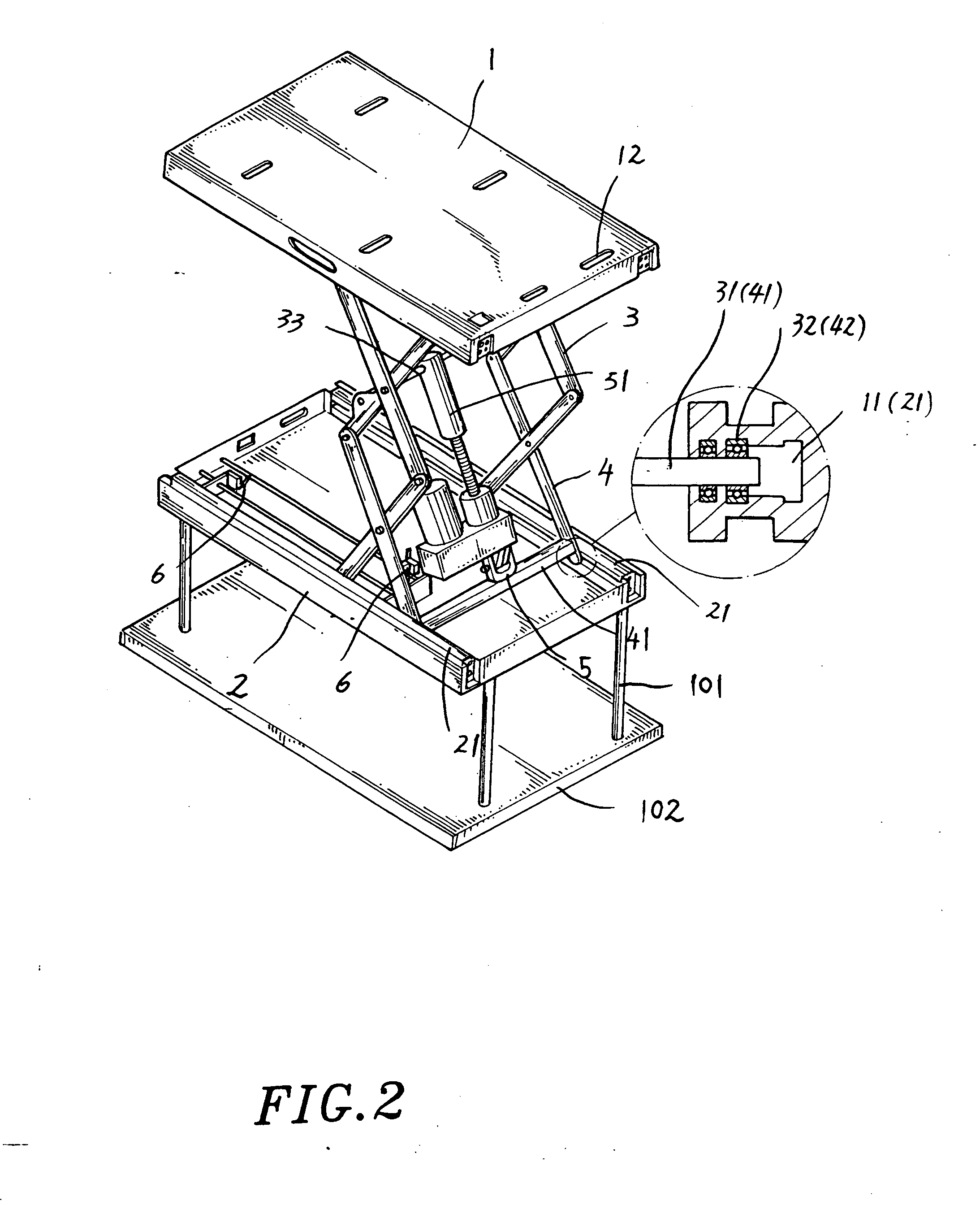
[0019] Referring to FIGS. 2 and 3, the present invention comprises upper and lower frame bodies 1, 2, a track disposed longitudinally along the lateral sides of the upper and lower frame bodies 1, 2 respectively, so that upper and lower braking rods 3, 4 crossed with each other are connected to the upper and lower frame bodies 1, 2; wherein transversal rods 31, 41 are disposed separately at the top of the upper braking rod 3 and the bottom of the lower braking rod 4, and bearings 32, 42 are disposed separately on both ends of the transversal rods 31, 41, such that the bearings 32, 42 are disposed in the tracks 11, 21 respectively and can slide along the tracks 11, 21.

[0020] The transversal rod 41 disposed at the bottom of the lower braking rod 4 is fixed to an electric screw rod 51 by a U-shape fixing plate 5, so that the front end of the screw rod 51 is connected to a transversal rod 33 disposed at the intersection of the upper braking rod 3. When the screw rod 51 is extended or w...


PUM


Abstract

An improved hidden electric power elevating stand structure includes upper and lower symmetric frame bodies, and upper and lower braking rods crossed with each other for fixing the upper and lower frame bodies on their lateral sides longitudinally, a transversal rod disposed at the bottom of the lower braking rod, a bearing installed separately on both sides of the transversal rod, such that the bearing is connected to a sliding track on both sides of the lower frame body, an electric power screw rod connects one of the transversal rods of the lower braking rod to the intersection of the upper braking rod, so that the extension and withdrawal of the screw rod change the intersecting angle of the braking rods and adjust the elevation of the frame bodies for placing an audio / video equipment such as a projector or a speaker. Symmetric microswitches are installed on the internal side of the track at the lower frame body to define the limit position for displacement and an elevator is installed on a detachable fixing stand to facilitate the construction and adjust the angle of elevation and the level of the stand.

Description

BACKGROUND OF THE INVENTION [0001] 1. Field of the Invention [0002] The present invention relates to an improved hidden electric power elevating stand structure, and more particularly to an easy-to-install, easy-to-operate, power saving and stable elevating stand structure that can be hidden in a ceiling. [0003] 2. Description of the Related Art [0004] In general, the traditional stand for placing a videoconferencing or audio / video equipment such as an overhead projector, a speaker and an optical disk drive is not adjustable regardless of being fixed at a certain height or suspended from a ceiling. Furthermore, objects like an overhead projector usually require an adjustment of their heights according to the actual situations, and thus manufacturers design an elevating stand that can be controlled by a remote control. An example is depicted in FIG. 1 and disclosed in R.O.C. Pat. No. 87204069. The elevating stand comprises two frames, a cross frame panel installed between the two fra...

Claims


Application Information

Patent Timeline
Patent Type & Authority Applications(United States)
IPC IPC(8): A47B9/00
CPCB66F7/0608B66F7/0666B66F7/065
Inventor LO, WEN-PING
Owner LO WEN PING
Why Eureka
Try Eureka