Ultrasonic device for cleaning connectors

a technology of ultrasonic devices and connectors, applied in the direction of line connector maintenance, cleaning using liquids, flexible article cleaning, etc., can solve the problems of connector coupling loss, poor fiber alignment, and possible connector attenuation. serious issu

Inactive Publication Date: 2007-02-15
HARRIS CORP
View PDF4 Cites 15 Cited by
  • Summary
  • Abstract
  • Description
  • Claims
  • Application Information

AI Technical Summary

Benefits of technology

[0008] According to one aspect of the method, a containment structure can be chosen that has a port which is sized and shaped for mating with the exposed end of the connector. Further, a seal can...

Problems solved by technology

The attenuation potentially introduced by a connector can be a serious issue, particularly at microwave RF frequencies and in the optical fiber field.
Connector coupling loss can result from a number of mechanisms.
For example, in the fiber optic area, poor fiber alignment and improper end preparation are known to increase insertion loss.
However, dust, dirt, moisture, grease, and any of a wide variety of other contaminants, can also have a significant impact on signal attenuation with regard to both RF and optical signals.
Still, connectors can a...

Method used


Image

  • Ultrasonic device for cleaning connectors
  • Ultrasonic device for cleaning connectors
  • Ultrasonic device for cleaning connectors

Examples


Embodiment Construction

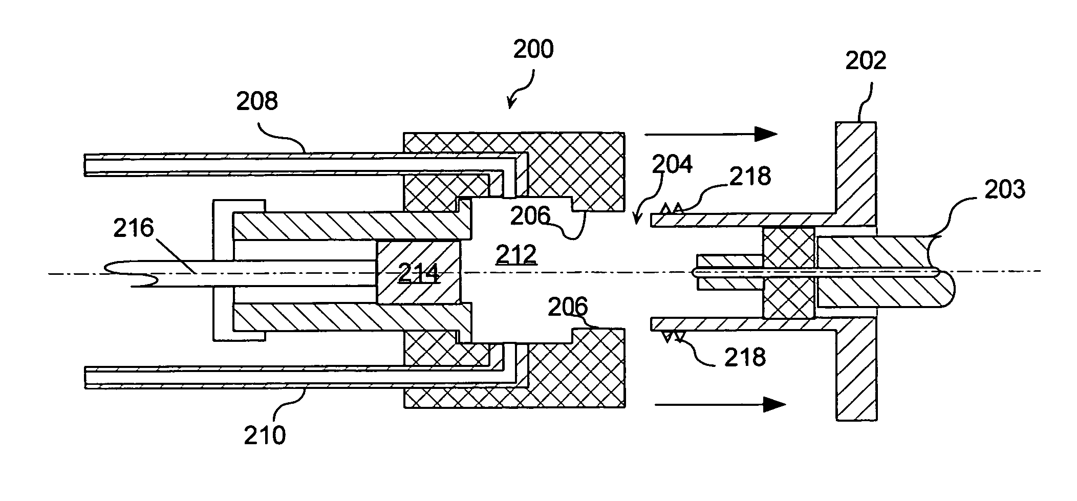
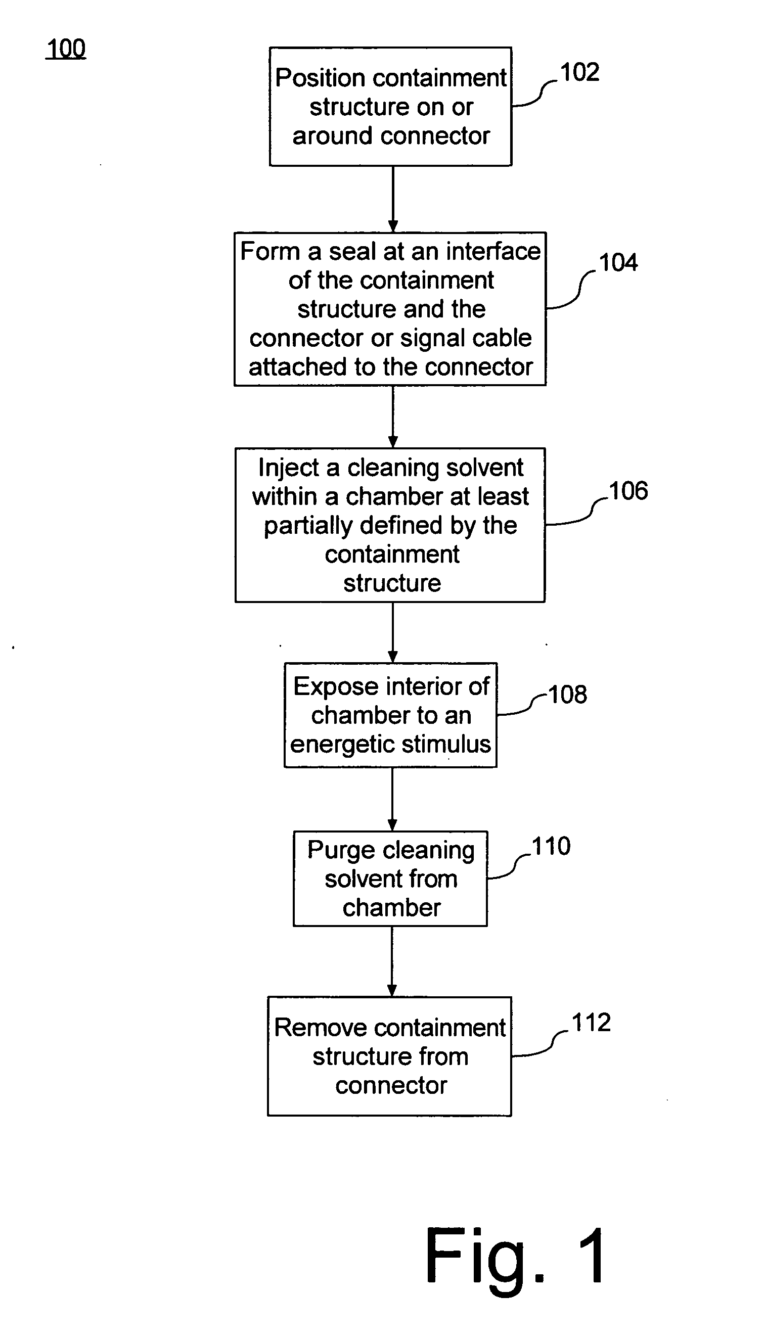
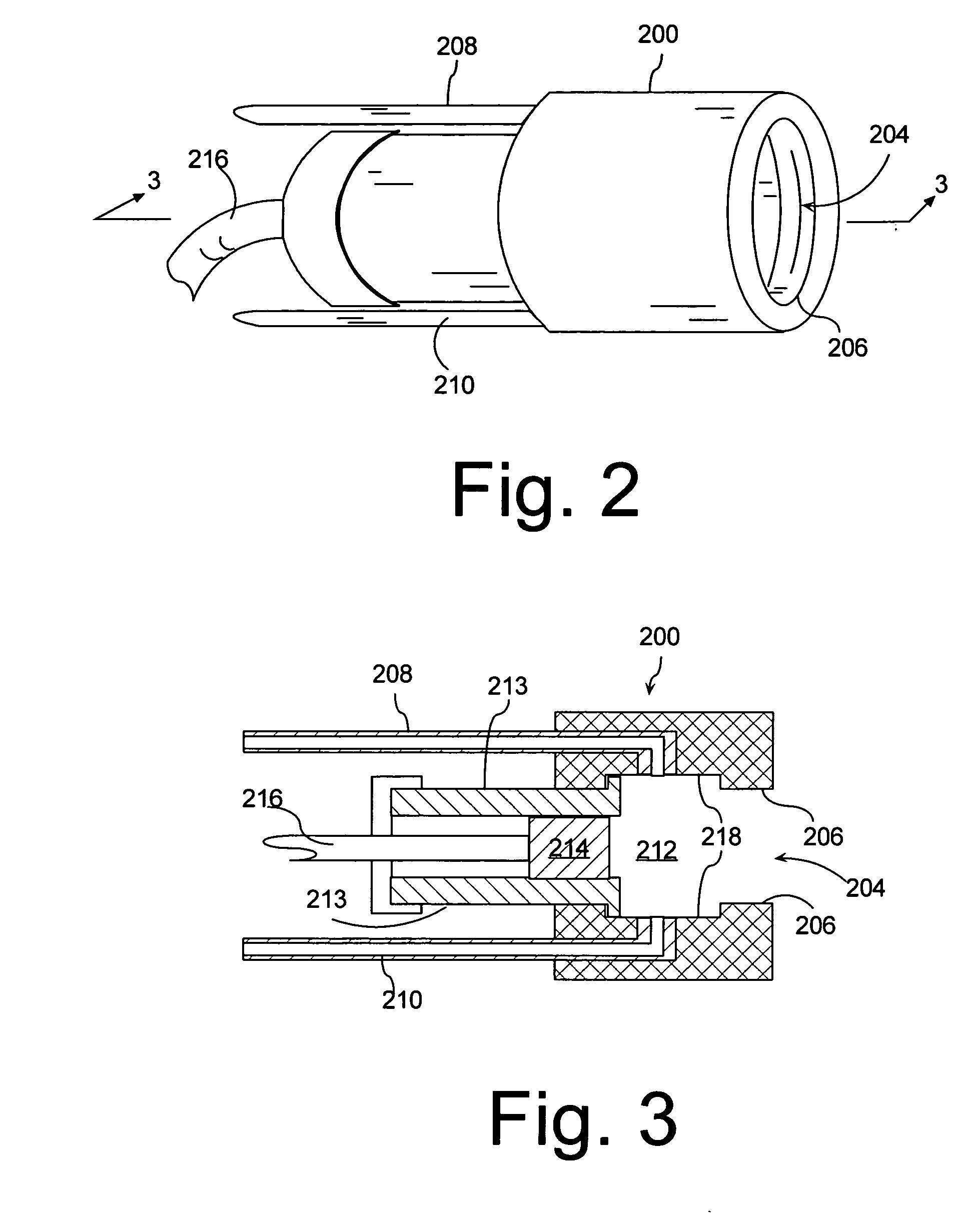
[0024] A method for cleaning a connector shall now be described in relation to flowchart 100 which is shown in FIG. 1. The method can begin in step 102 by positioning a containment structure on or around a portion of a connector. The connector can be, without limitation, a fiber-optic connector, an RF connector, an electrical connector, or an electro-optical connector.

[0025] The containment structure can have a variety of different designs that are suited for receiving the connector in step 102. However the containment structure should be arranged so that at least that portion of the connector that requires cleaning is received within the containment structure in step 102. For example, the containment structure can be configured to receive an exposed end of a connector, the entire connector, or any other portion of the connector. Regardless of the selected portion of the connector that is received in the containment structure in step 102, the containment structure can form at least...


PUM


Abstract

A method and apparatus for cleaning a connector. The method includes several steps including: positioning a containment structure on an exposed end of a connector, and injecting a cleaning solvent within a chamber defined by the containment structure and the exposed end. Thereafter, the interior of the chamber containing the cleaning solvent can be exposed to an energetic stimulus, such as ultrasonic acoustic energy. After the ultrasonic energy has been applied, the solvent can be removed from the chamber.

Description

BACKGROUND OF THE INVENTION [0001] 1. Statement of the Technical Field [0002] The inventive arrangements concern cleaning devices, and more particularly devices that are useful for cleaning electronic, optical, and electro-optical connectors. [0003] 2. Description of the Related Art [0004] Military and commercial applications increasingly rely upon a wide variety of electronic, RF, optical and electro-optical connectors for communicating signals within systems and across platforms. In general, such connectors consist of an interlocking structure that permits the coupling of electrical conductors, optical fibers or a combination of the two. [0005] It is important that connectors do not attenuate the electrical, RF and optical signals they are intended to carry. The attenuation potentially introduced by a connector can be a serious issue, particularly at microwave RF frequencies and in the optical fiber field. Connector coupling loss can result from a number of mechanisms. For example...

Claims


Application Information

Patent Timeline
IPC IPC(8): B08B3/12B08B9/00
CPCB08B3/12H01R43/002B08B11/00
Inventor HESCH, LEONARD T. JR.LEICHLITER, AMELIA C.
Owner HARRIS CORP
Why Eureka
Try Eureka