Load control for stump cutter

a technology of load control and stump cutter, which is applied in the field of rotating stump cutters, can solve the problems of damage to the stump cutter, inability to completely avoid additional load on the engine, and the present load control system used on traditional stump cutters is not effective on these newer stump cutters

Inactive Publication Date: 2007-02-15
RAYCO MFG
View PDF13 Cites 16 Cited by
  • Summary
  • Abstract
  • Description
  • Claims
  • Application Information

AI Technical Summary

Problems solved by technology

One of the problems that arises during the operation of a stump cutter relates to the load experienced by the cutter wheel.
If the increased load exceeds a certain value, it may cause damage to the stump cutter.
While this damage may occur to various elements of the stump cutter, one of the greatest concerns is overloading the engine which drives the stump cutter.
One of the major problems that arises from such stump cutters and related load control systems relates to the engine speed being directly related to the cutter wheel speed.
Thus, there is no way to completely avoid additional load to the engine when the cutter wheel experiences an increased load.
Because these stump cutters do not have a direct relation between the engine speed and the cutter wheel speed, the present load control systems used on traditional stump cutters are not effective on these newer stump cutters.

Method used


Image

  • Load control for stump cutter
  • Load control for stump cutter
  • Load control for stump cutter

Examples


Embodiment Construction

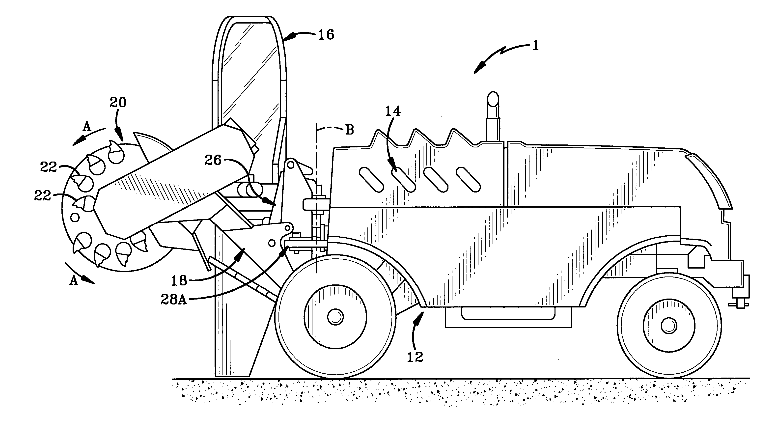
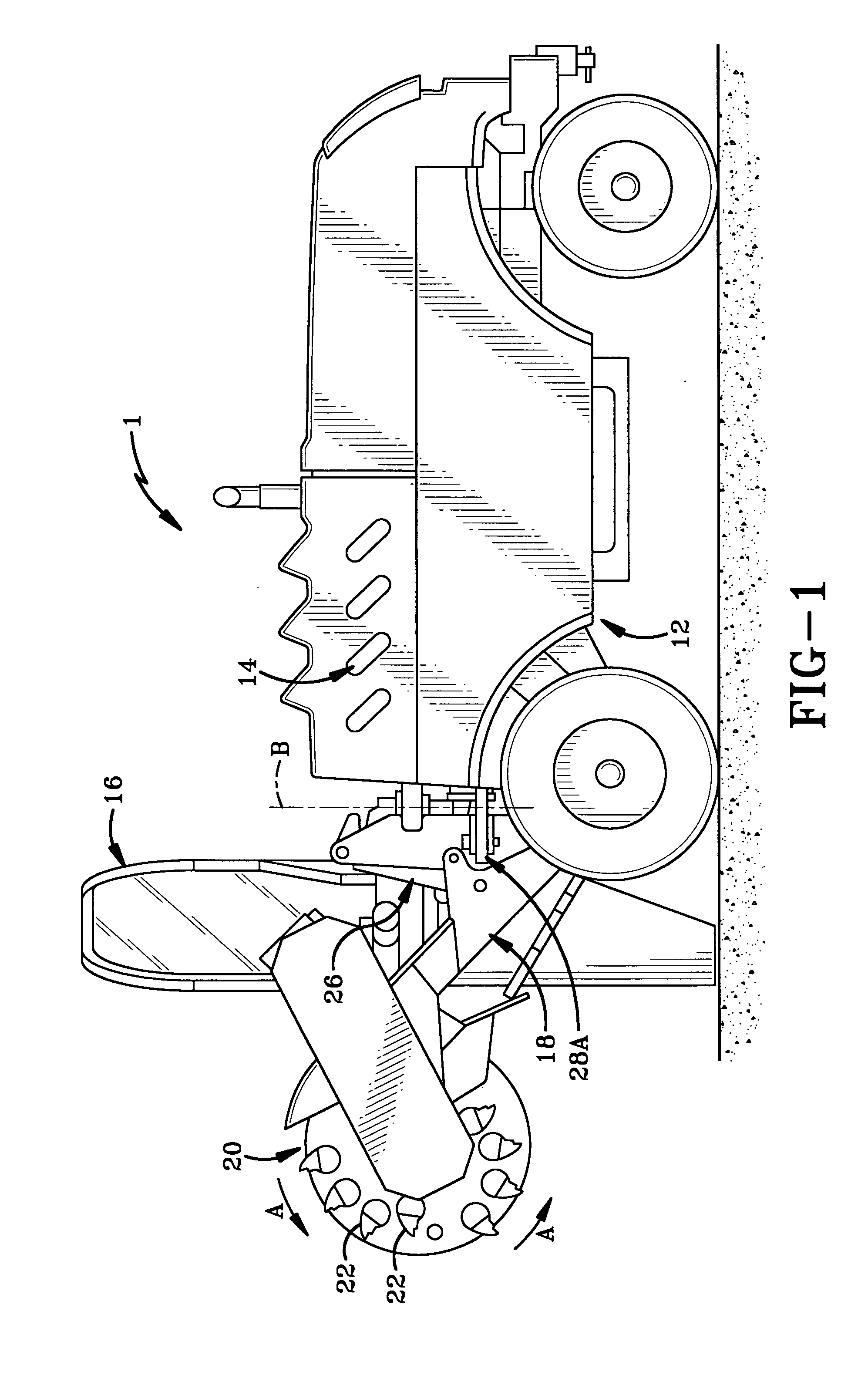
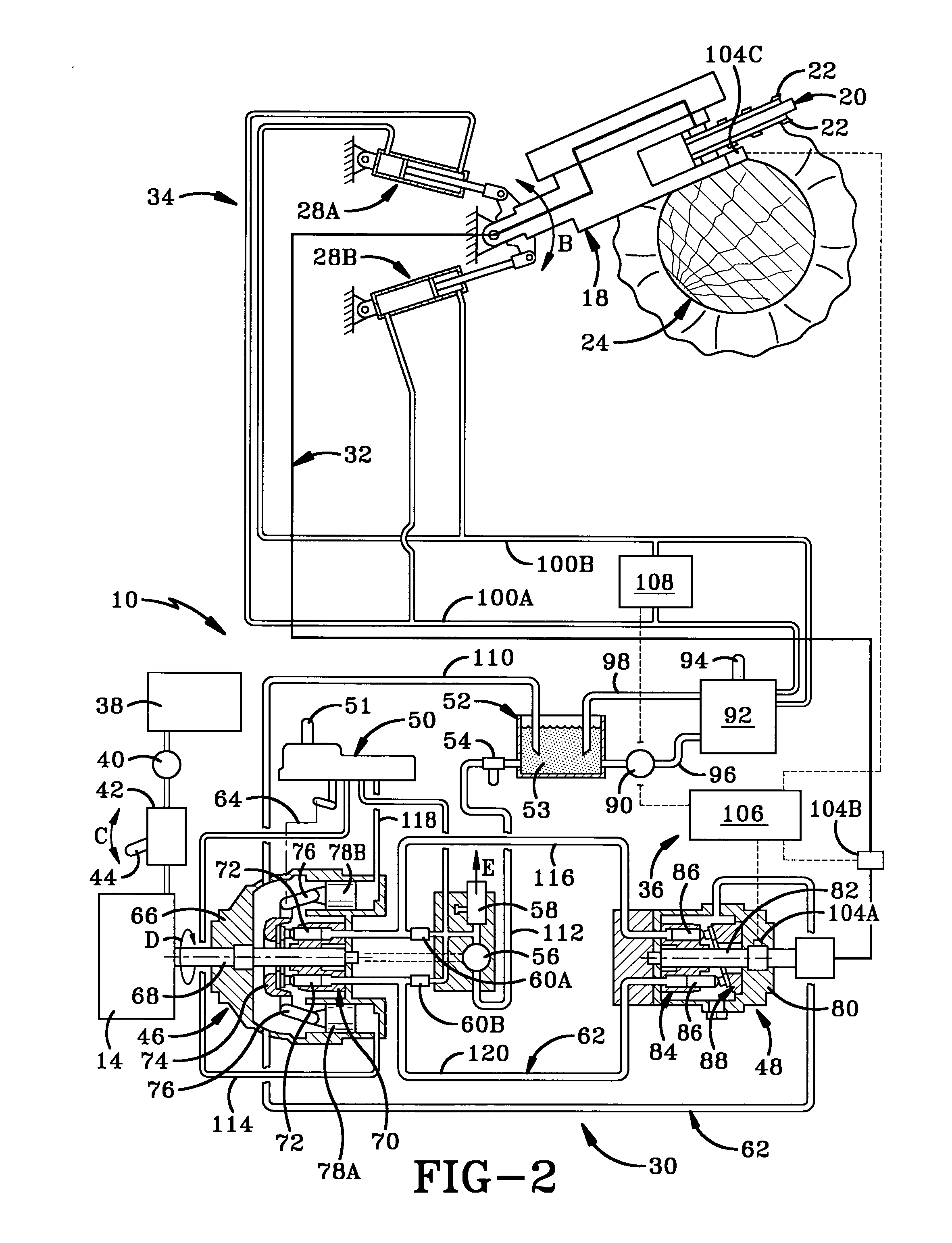
[0021] The stump cutter of the present invention is indicated generally at 1 in FIG. 1 and the power and load control system of the present invention is indicated generally at 10 in FIG. 2. Referring to FIG. 1, stump cutter 1 is a wheeled vehicle having a frame 12 with an engine 14 mounted thereon. A control panel 16 is pivotally mounted on frame 12 for controlling various movements of stump cutter 1. A boom 18 is movably mounted on frame 12 and supports a cutter wheel 20 rotatably thereon as indicated by Arrows A. A plurality of cutting teeth 22 are mounted on each side of cutter wheel 20 for cutting a stump 24 (FIG. 2) upon rotation of cutter wheel 20.

[0022] With continued reference to FIG. 1, boom 18 and cutter wheel 20 are more particularly movable in an upward and downward direction by operation of an actuator 26 which is typically a hydraulically driven piston-cylinder combination. In addition, boom 18 and cutter wheel 20 are movable laterally or in a side-to-side fashion. Th...


PUM


Abstract

A load control system controls movement of a cutter wheel of a stump cutter wherein the cutter wheel rotates at a rotational speed independent of the rotational speed of an engine which powers the stump cutter. The stump cutter includes a hydrostatic transmission having a variable displacement hydraulic pump whereby the rotational speed of the cutter wheel is independent of that of the engine. The load control system includes a sensor for directly or indirectly sensing the rotational speed of the cutter wheel, a microprocessor for determining a response to changes in cutter wheel rotational speed and trim valves for controlling the feed rate of the cutter wheel.

Description

BACKGROUND OF THE INVENTION [0001] 1. Technical Field [0002] The invention relates generally to machines having rotating cutters. More particularly, the invention relates to a stump cutter having a maneuverable cutter wheel with cutting teeth mounted thereon. Specifically, the invention relates to a stump cutter having a hydraulically driven cutter wheel and a load control or feed rate control mechanism. [0003] 2. Background Information [0004] Stump cutters generally have cutting teeth on the side of a rotating disc known as the cutter wheel. Thus, the side of the wheel is fed laterally into the stump, usually by pivoting the boom on which the cutter wheel is rotatably mounted. Actuators which are typically hydraulically driven control the feed rate of this lateral movement. In addition, the cutter wheel may be moved up and down and fore and aft. The present invention is concerned with all these movements, but most particularly with the lateral or side-to-side movement of the cutter...

Claims


Application Information

Patent Timeline
Patent Type & Authority Applications(United States)
IPC IPC(8): A01G23/06B27B1/00B23Q15/00B27M3/00B23Q16/00
CPCA01G23/067
Inventor CHAPMAN, BRUCE G.
Owner RAYCO MFG
Why Eureka
Try Eureka