Article transport device

a technology for transporting devices and objects, applied in the direction of lighting and heating apparatus, charge manipulation, furniture, etc., can solve the problems of large and complex configuration of the transferring means of objects

Inactive Publication Date: 2007-02-15
DAIFUKU CO LTD
View PDF8 Cites 309 Cited by
  • Summary
  • Abstract
  • Description
  • Claims
  • Application Information

AI Technical Summary

Benefits of technology

[0020] With the device according to the present invention, it is possible to make the configuration for delivering an article at an article delivering location or receiving an article at an article receiving location smaller and simpler than that of conventional devices.

Problems solved by technology

Since it is necessary to move the placing portion over a long distance, the article transferring means has a large and complex configuration.

Method used


Image

  • Article transport device
  • Article transport device
  • Article transport device

Examples


first embodiment

[0048] First, a first embodiment is described.

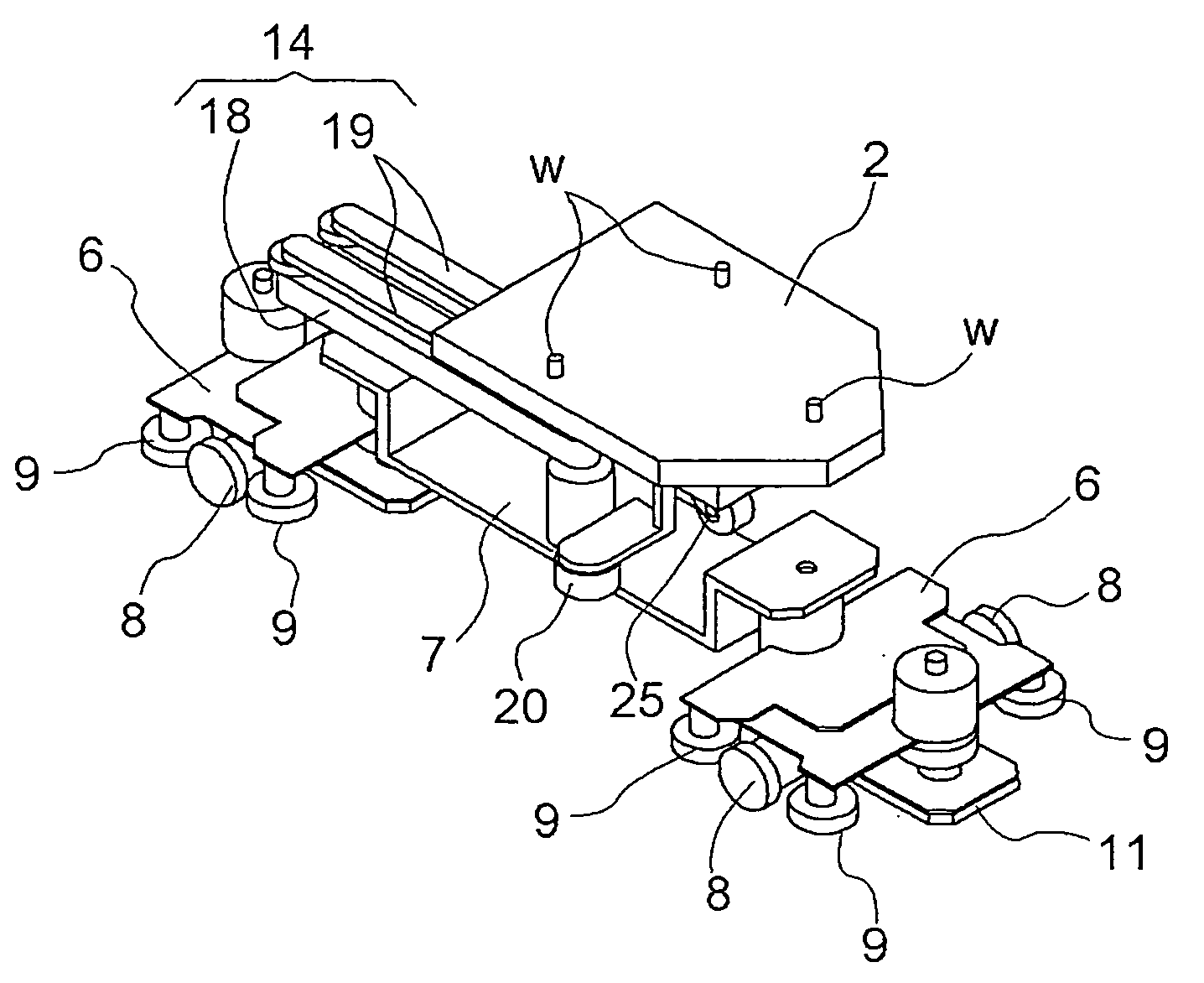
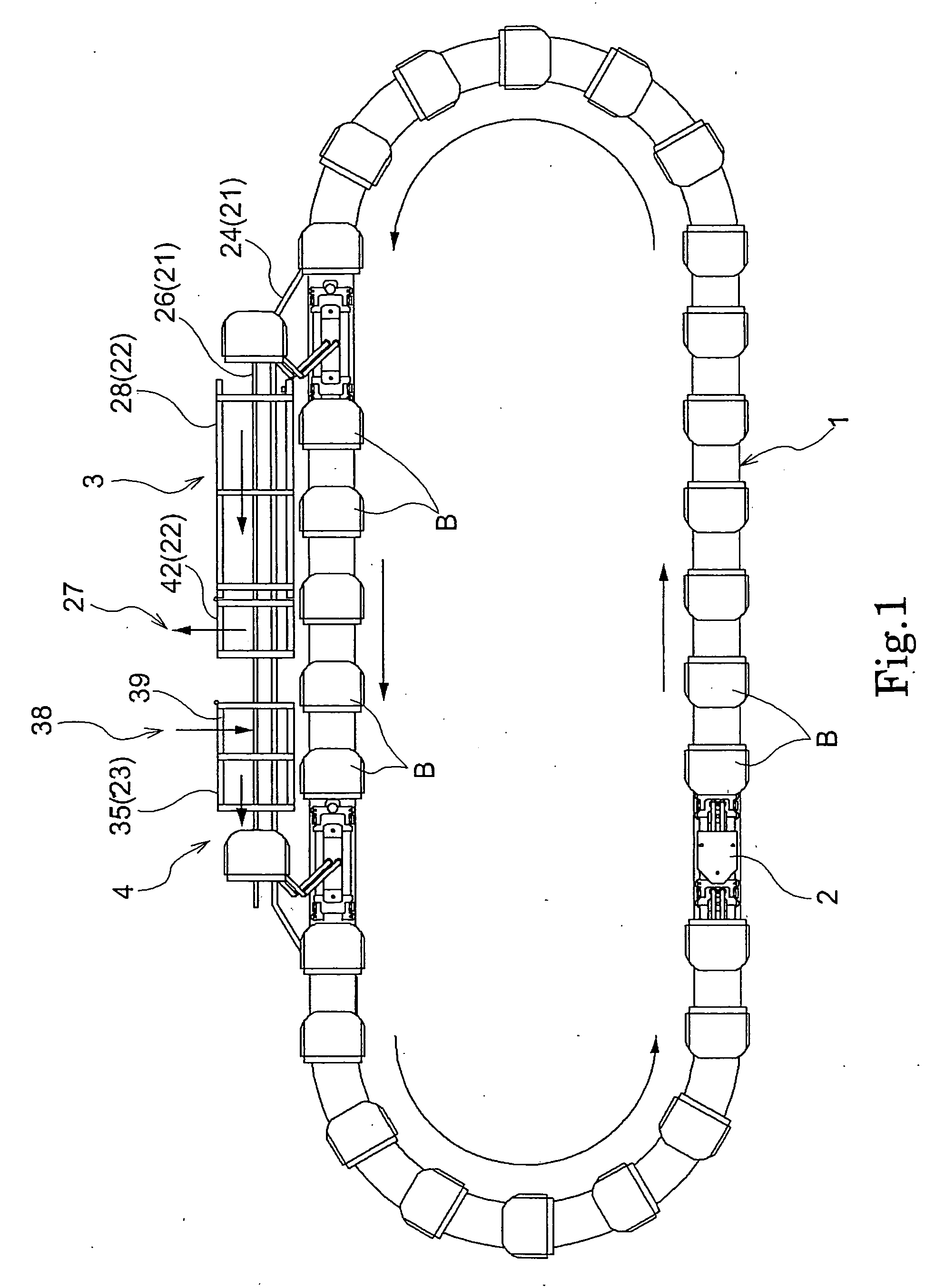
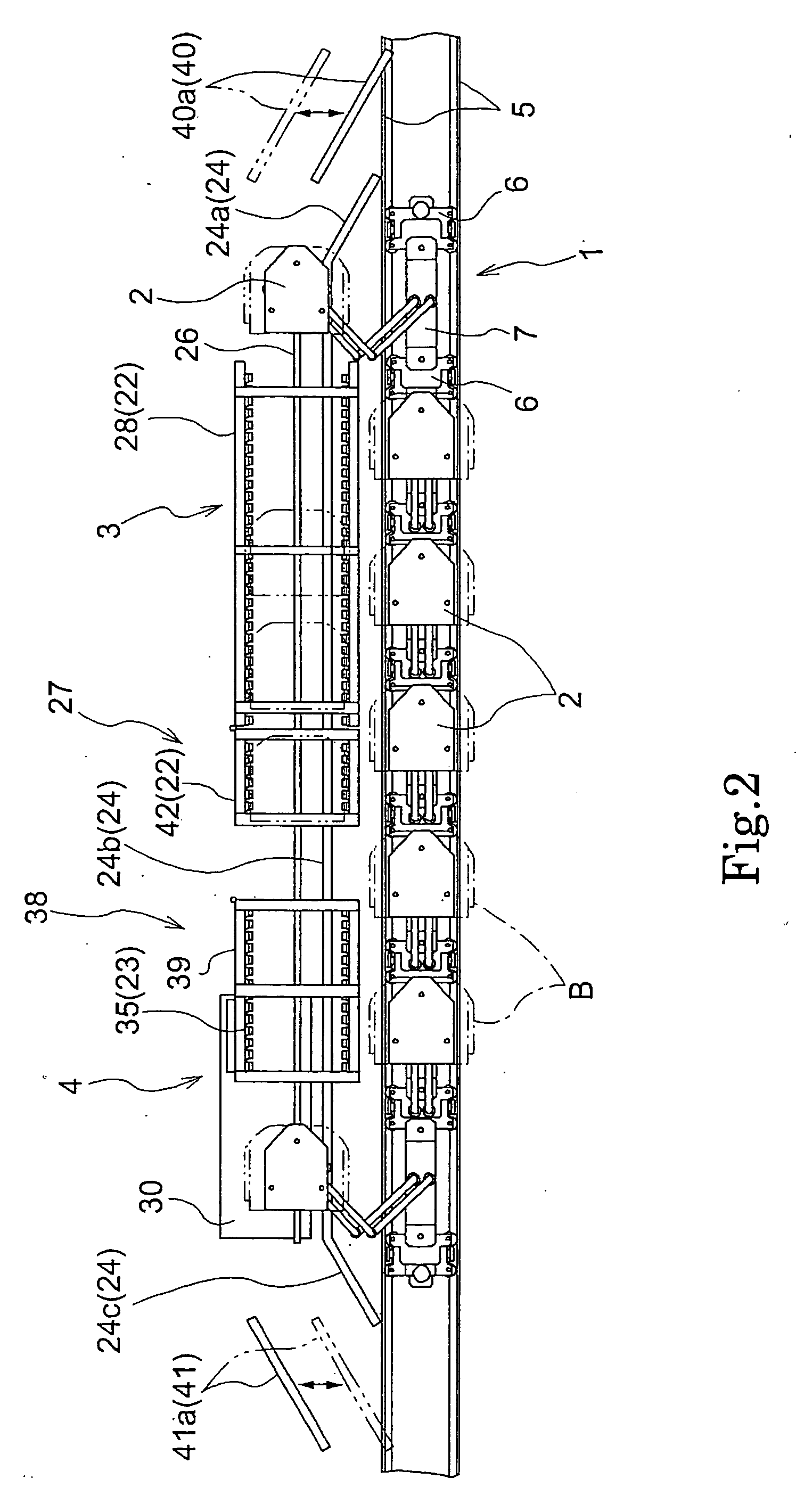
[0049] As shown in FIGS. 1 to 3, an article transport device of the first embodiment is constituted by a plurality of article placing members 2 (article supports) on which articles B are placed and supported, and an endless revolving body 1 that revolves in a circular manner in the horizontal direction or a substantially horizontal direction. The article placing members 2 are aligned apart from each other in the longitudinal direction of the endless revolving body 1, and move together with the endless revolving body 1.

[0050]FIG. 1 is an overall plan view of the article transport device. FIG. 2 is a plan view showing the main portions of the article transport device. FIG. 3 is a perspective view showing the main portions of the article transport device.

[0051] A revolving path of the endless revolving body 1 is provided with an article delivering location 3 for delivering articles B to various article handling facilities such as an arti...

second embodiment

[0144] Next, a second embodiment is described.

[0145] The second embodiment is another embodiment concerning the configuration in which the article placing member 2 that is positioned at the transport position is moved to the fork-middle position and the configuration in which the article placing member 2 that is positioned at the merging-middle position is moved to the transport position in the first embodiment. These configurations are described in detail, and a detailed description of the other configurations has been omitted.

[0146] First, a configuration is described in which the article placing member 2 that is positioned at the transport position is moved to the fork-middle position.

[0147] In the first embodiment, as shown in FIG. 2, is provided the fork-switching means 40 including the fork guide rail 40a that can horizontally move between the guide position at which the article placing member 2 that is positioned at the transport position is moved from the transport positi...


PUM


Abstract

An article transport device comprises an endless revolving body that is configured to move along a cyclic path in a substantially horizontal direction; a plurality of article supports each of which supports an article, wherein the article supports move together with the endless revolving body with the supports spaced apart from each other in a traveling direction; a support mechanism for supporting the article supports to the endless revolving body such that the article supports can move between a transport position adjacent the endless revolving body and an away position spaced apart from the transport position; and a guide mechanism for causing at least some of the article supports to move from the transport position to the away position and to move from the away position to the transport position, at an article delivering location or an article receiving location along the cyclic path of the endless revolving body.

Description

BACKGROUND OF THE INVENTION [0001] 1. Field of the Invention [0002] The present invention relates to article transport devices. [0003] 2. Description of Related Art [0004] Article transport devices have an endless revolving body that is configured to move along a cyclic path in a substantially horizontal direction and a plurality of article supports each of which supports an article. The plurality of article supports move together with the endless revolving body with the supports spaced apart from each other in a traveling direction. [0005] Such article transport devices are used for transporting articles such as transport containers that contain semiconductor substrates to and from various article handling facilities such as article storage facilities that store the articles. [0006] A revolving path in the endless revolving body is provided with an article delivering location for delivering articles to an article handling facility and an article receiving location for receiving art...

Claims


Application Information

Patent Timeline
Patent Type & Authority Applications(United States)
IPC IPC(8): B65G1/00B65G47/46
CPCH01L21/67715H01L21/67736H01L21/6773
Inventor INUI, YOSHITAKA
Owner DAIFUKU CO LTD
Why Eureka
Try Eureka