Fuel-cell actuated mechanical device

a mechanical device and fuel cell technology, applied in the field of reversible fuel cells, can solve the problems of slow recombination, uncontrollable, and inability to use reclaimable reagents,

Inactive Publication Date: 2007-02-15
MITSUBISHI ELECTRIC RES LAB INC
View PDF5 Cites 11 Cited by
  • Summary
  • Abstract
  • Description
  • Claims
  • Application Information

AI Technical Summary

Problems solved by technology

However, that recombination is slow and uncontrolled.
Additionally, the uncontrolled recombination of hydrogen and oxygen in that way generates heat, which is not usefully reclaimable.
Ho

Method used


Image

  • Fuel-cell actuated mechanical device
  • Fuel-cell actuated mechanical device
  • Fuel-cell actuated mechanical device

Examples


Embodiment Construction

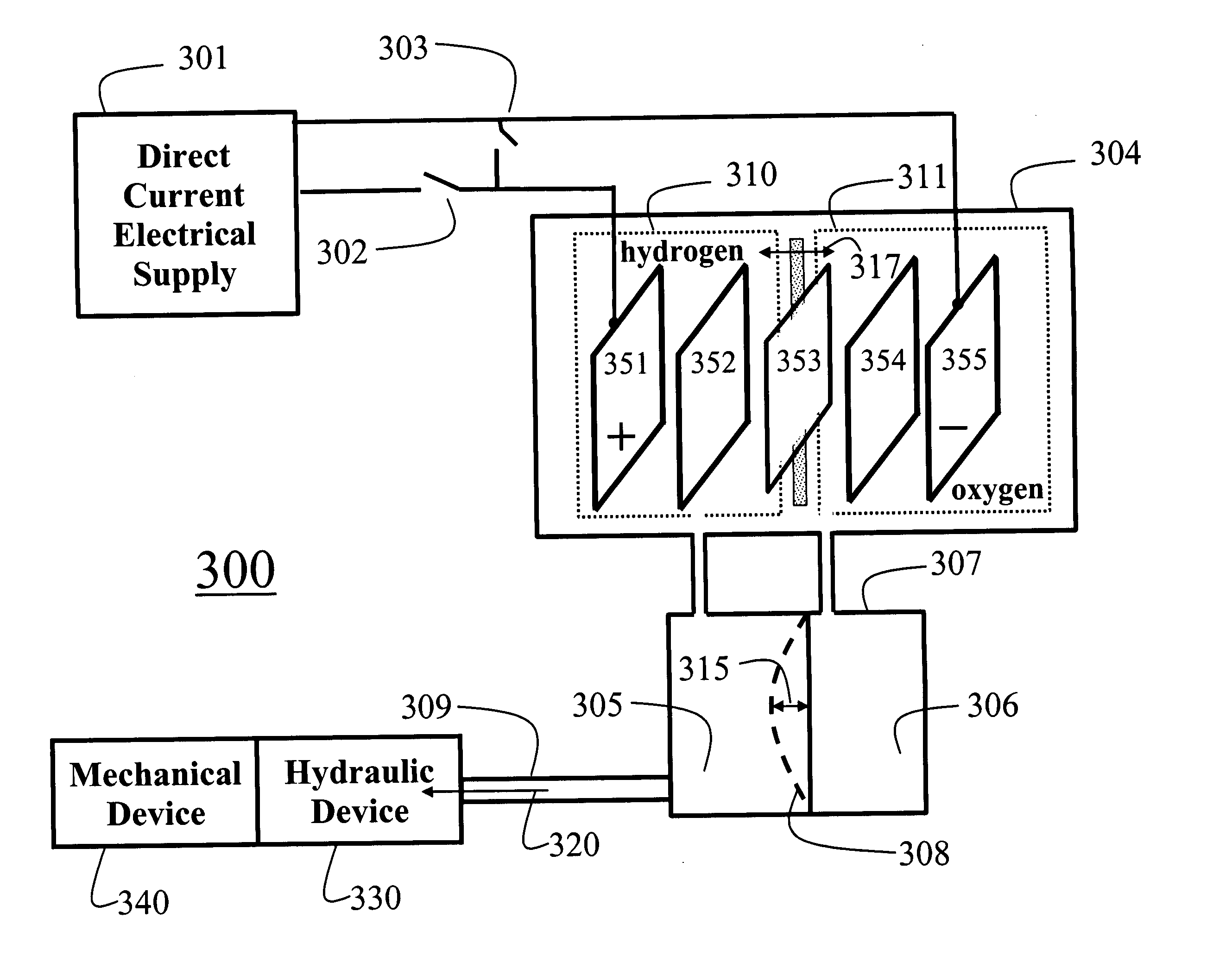
[0034] System Structure

[0035]FIG. 3A shows a fuel-cell actuated mechanical energy generating device 300 according to one embodiment of the invention. The device includes a fuel-cell 304 coupled to a pressure equalization device 307, which is coupled to a hydraulic device 330, which is optionally coupled to a mechanical device 340. As defined herein, the fuel-cell, pressure equalization device and hydraulic device form a ‘closed’ system for storing water. That is, during operation no water enters or exits the closed system.

[0036] The fuel-cell 304 includes a positive electrode 351, a positive porous conductor 352, a pervious proton exchange membrane 353, a negative porous conductor 354, and a negative electrode 355. The mechanical energy generating device 300 also includes a direct current power supply 301 connected serially to a pass switch 302, and in parallel to a shunt switch 303. The switches 302-303 enable the fuel-cell 304 to be powered electrically to cause electrolysis to ...


PUM

PropertyMeasurementUnit
Electric energyaaaaaaaaaa
Pressureaaaaaaaaaa
Flexibilityaaaaaaaaaa

Abstract

A method generates mechanical energy by storing water in a fuel-cell and a pressure equalization device. The water stored in the fuel-cell is electrolyzed into hydrogen gas and oxygen gas, which displaces the water stored in the pressure equalization device. The displaced water is fed to a hydraulic device to drive the hydraulic device in a forward direction to produce mechanical energy.

Description

FIELD OF THE INVENTION [0001] The invention relates generally to fuel-cells, and more particularly to reversible fuel-cells. BACKGROUND OF THE INVENTION [0002] Fuel-Cell [0003] A fuel-cell reaction can be expressed as: [0004] 2H2O+electrical energy⇄2H2+O2+potential electric energy. [0005] A forward reaction of electrolysis consumes water (H2O) and outgases hydrogen (H2) and oxygen (O2). A back reaction of hydrogen and oxygen produces water and potential electric energy, i.e., the so called‘fuel-cell’ reaction. [0006]FIG. 1 shows a typical prior art reversible fuel-cell 100. A direct current power supply 110 supplies current through wires 120 to electrodes 130 inside an electrolysis cell 140. The current electrolyzes water 150 in the electrolysis cell 140 to produce a mixture of gaseous hydrogen and oxygen 160 which flow through an interconnecting tube 170 to a reagent reservoir 180. This pressurizes a liquid reagent 190, forcing the reagent to flow out from the reservoir via a tube ...

Claims


Application Information

Patent Timeline
IPC IPC(8): C25C1/02C25B1/02
CPCF04B17/00F04B19/24F04B43/04F04B43/06H01M8/04104H01M8/0656Y02E60/56H01M2008/1095H01M2250/40H01M2250/407Y02E60/366Y02E60/528Y02E60/563H01M8/186Y02E60/36Y02E60/50
Inventor YERAZUNIS, WILLIAM S.LAU, KING TONGSHEPHERD, RODERICK L.
Owner MITSUBISHI ELECTRIC RES LAB INC
Why Eureka
Try Eureka