Continuous molding of fastener products and the like and products produced thereby

a technology of fastener products and products, applied in the direction of filament/thread forming, layered products, other domestic articles, etc., can solve the problems of small separation between adjacent mold plates, undesirable variation in the thickness of the base layer across the width of the product, and limited bending resistance of the mold roll, so as to achieve uniform product thickness.

Inactive Publication Date: 2007-02-15
VELCRO IND BV
View PDF2 Cites 17 Cited by
  • Summary
  • Abstract
  • Description
  • Claims
  • Application Information

AI Technical Summary

Benefits of technology

[0003] We have realized that many advantages can be obtained by employing longer mold rolls and correspondingly wide pressure zones to form wide products, while providing means to accommodate effects of the distribution of pressure along the length of the mold roll. By this means, products molded with wide widths can have uniform product thickness and other properties previously found only in narrower materials.
[0004] We also have realized that many advantages can be obtained by raising the pressure in the pressure zone, with a conventional roll or a longer roll, to form products having finer features while providing means to accommodate effects of the distribution of pressure along the length of the mold roll.
[0039] According to another aspect of the invention, a method of continuously molding fastener elements on one broad side of a sheet product opposite another broad side having surface features, e.g., raised or indented portions, is provided. The method comprises providing an apparatus that includes a mold roll, resiliently deformable pressure roll, and an extruder die, all as described above, passing a sheet product having the surface features through the nip with the molten resin such that the resilient surface of the pressure roll conforms in the vicinity of the features to protect the features as they pass through the nip. The method also includes forming fastener elements integral with a base web on a broad side of the sheet product.
[0042] Various aspects of the invention disclosed here enable cost-effective commercialization of molded fastener products of extremely wide widths and products having many very small fastener elements. In particular, fastener products with very thin base layer thicknesses held to very close dimensional tolerances can be produced in a practical manner. According to another aspect of the invention, the contact from loading systems that are provided according to the invention in the form of load rolls or load belts, are advantageously employed to extract heat from the back of the base layer of the product, to enable production of thicker base layers or to produce a product with a given base thickness at a much higher production speed than has previously been possible.

Problems solved by technology

We have realized that, because of the construction of the molding region of the mold roll as a stacked series of rings or plates about a central shaft, the mold roll has limited bending resistance.
As a result, if the molding region of the mold roll is made long to produce a wide product, or if the pressure of the resin is increased, the tendency of the mold roll to bend away from the pressure zone under the extreme molding pressure can cause small separations between adjacent mold plates and undesirable base layer thickness variation across the width of the product (i.e. gap variation along the length of the molding region).
Also, we realize that non-uniform geometry of the pressure zone can produce detrimental nonuniformity in the pressure distribution across the pressure zone, which can lead to incomplete filling of some of the mold cavities.

Method used


Image

  • Continuous molding of fastener products and the like and products produced thereby
  • Continuous molding of fastener products and the like and products produced thereby
  • Continuous molding of fastener products and the like and products produced thereby

Examples


Embodiment Construction

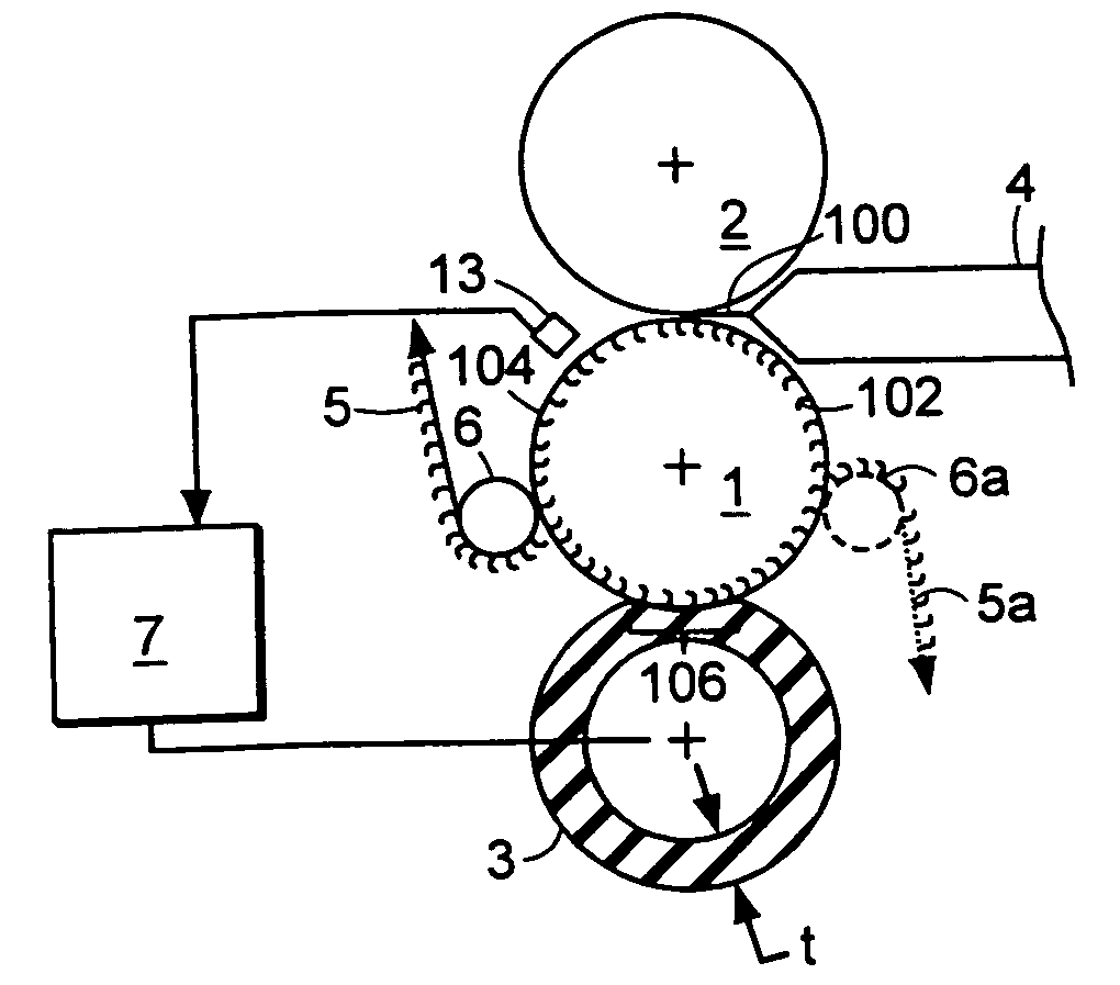
[0075] Referring to the embodiment of FIG. 1, an extruder 4 delivers a wide extrusion of molten polymer 100 into the nip (i.e. into the pressure zone) between an elongated mold roll 1 and a pressure roll 2. The polymer is forced into fastener-shaped cavities 102 by the pressure of the nip, forming a base layer with integral fastener elements. The fastener elements are, in some cases, fully-formed elements capable of snagging loops as molded. In other cases, the fastener elements are preform elements that are intended to be subjected to a post-forming operation to form completed fastener elements. The post-forming operation, in some cases, forms flat top portions on hook or post preforms. The fastener elements are very small to engage small loops or fibers on a surface, and typically are arranged on the web base with a density of 500 to 2,000 fastener elements per square inch.

[0076] The fastener product 5 is carried on the chilled mold roll 1 a distance sufficient to solidify the fa...


PUM

PropertyMeasurementUnit
depthaaaaaaaaaa
depthaaaaaaaaaa
diameteraaaaaaaaaa

Abstract

Improvements are disclosed for an apparatus for continuously molding small fastener elements integral with a base web from a flowable resin. The apparatus comprises a cylindrical mold roll rotatable about an axis and defining small fastener element-shaped mold cavities in the surface thereof, and pressure-applying means to apply operating pressure to force the resin into the cavities at a pressure zone. The pressure-applying means and mold roll define a mold gap therebetween for forming the base web. The advantageous use of relatively long mold rolls, to produce a correspondingly wide web, and the use of higher molding pressures, e.g. to form very small fastener elements, is enabled by various improvements, including means to maintain the mold gap at a desired thickness profile across the length of the molding region of the mold roll under operating pressure. In some cases the pressure-applying means includes a pressure roll, in other cases it includes a resin nozzle assembly or pressure head. In some other cases it includes a belt. Various control schemes are also disclosed, as are means to provide cooling. In some particularly useful embodiments, at least one of the rolls of the apparatus has a resiliently deformable surface. Methods of molding fastener elements directly on a sheet material, such as sandpaper, are also disclosed, as well as methods for laminating.

Description

BACKGROUND OF THE INVENTION [0001] This invention relates to improved equipment and methods for making continuous fastener products and the like, and to products produced by the equipment and methods. [0002] Fastener products, such as hook components of hook-and-loop fasteners, are manufactured by a continuous molding method employing a cylindrical mold roll which has fastener-shaped cavities formed in its periphery. Often the mold roll is formed of an axially compressed stack of ring-form mold plates. In operation, molten polymer from an extruder is introduced into a pressure zone in which the molten polymer is forced under high pressure into the fastener cavities of the cooled mold roll, to form fastener elements (e.g. hooks) integrally molded with a base layer. In some cases the pressure zone is a nip formed by a mold roll and an adjacent pressure roll. In other configurations the pressure zone is formed between a conforming stationary pressure head and a mold roll. Typically, th...

Claims


Application Information

Patent Timeline
Patent Type & Authority Applications(United States)
IPC IPC(8): B29C47/00B29C43/38A41C1/10A44B18/00B29C43/22B29C43/46B29C43/58B29C48/08B29C59/02B29C59/04B32B5/30
CPCA44B18/0049A44B18/0061B29C43/222B29C47/0021B29C47/003B29C47/0033B29C2043/461B29C59/025B29C59/04B29C2043/465B29C2043/486B29L2031/729B29C43/46B29C47/32B29C48/08B29C48/12B29C48/13B29C48/35B29C48/92
Inventor HARVEY, ANDREW C.JENS, STEPHEN C.KINGSFORD, HOWARD A.NEUMANN, J. SCOTTFORMATO, RICHARD M.
Owner VELCRO IND BV
Why Eureka
Try Eureka