Dual-plunger energy switch

a dual-plunger, energy switch technology, applied in accelerators, klystrons, electric discharge tubes, etc., can solve the problems of low output in low energy mode, dose rate, internal structure cannot be optimized for multiple energies, etc., and achieve high output

Inactive Publication Date: 2007-02-15
SIEMENS MEDICAL SOLUTIONS USA INC
View PDF8 Cites 38 Cited by
  • Summary
  • Abstract
  • Description
  • Claims
  • Application Information

AI Technical Summary

Benefits of technology

[0007] Accordingly, the present invention is directed to a dual-plunger energy switch assembly for standing wave linear particle beam accelerators capable of operating in a higher energy mode and a lower energy mode. The dual-plunger energy switch assembly employs two mechanical plungers that can be extended different distances inside two side cells or cavities of the linear accelerator downstream of the RF input. When the linear accelerator is operated in the higher energy mode, both plungers are retracted out of the side cavities. To achieve high output while the linear accelerator is operated in the lower energy mode, the two plungers are radially inserted into the two side cavities to adjust the electromagnetic accelerating field along the length of the accelerator. For example, in a specific embodiment, one plunger is radially inserted into a side cavity so that the plunger touches the internal surface of the side cavity opposite the plunger assembly. The second plunger is radially inserted into a second side cavity so that the plunger is adjacent to, but not touching, the internal surface of the side cavity opposite the plunger assembly. In this manner, the dual-plunger energy switch assembly increases the output of the linear accelerator at lower energies without generating excessive heating, eliminating the need for water-cooling of the energy switch assembly. The energy switch assembly also does not require the use of side cavities having a special internal geometry. In specific embodiments, the dual-plunger energy switch assembly includes a common actuator assembly mechanically coupled to the plunger assemblies for positioning the plungers within the side cavities.

Problems solved by technology

Medical linear particle beam accelerators that operate at two or more energies suffer from the fundamental limitation that the internal structure cannot be optimized for multiple energies.
The lower gradient causes more electrons to be lost as they travel through the structure, resulting in loss of output in the low energy mode.
Prior energy switches achieve high dose rates at low energy, but, because of heating, require direct water-cooling of the plunger during operation.
Thus, the energy switches are vulnerable to water leaks and require multiple control system interlocks.

Method used


Image

  • Dual-plunger energy switch
  • Dual-plunger energy switch
  • Dual-plunger energy switch

Examples


Embodiment Construction

[0024] Reference will now be made in detail to the presently preferred embodiments of the invention, examples of which are illustrated in the accompanying drawings.

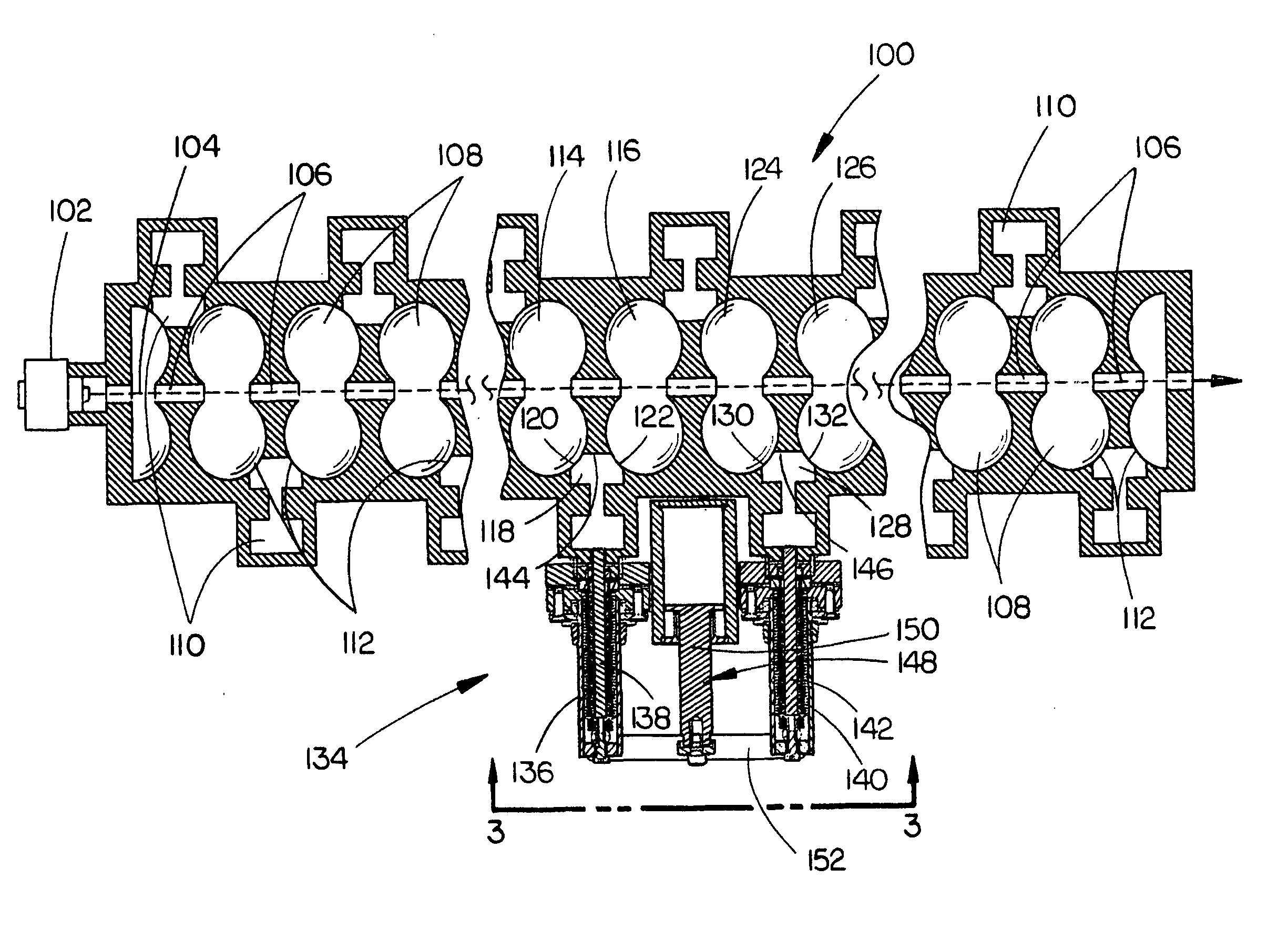
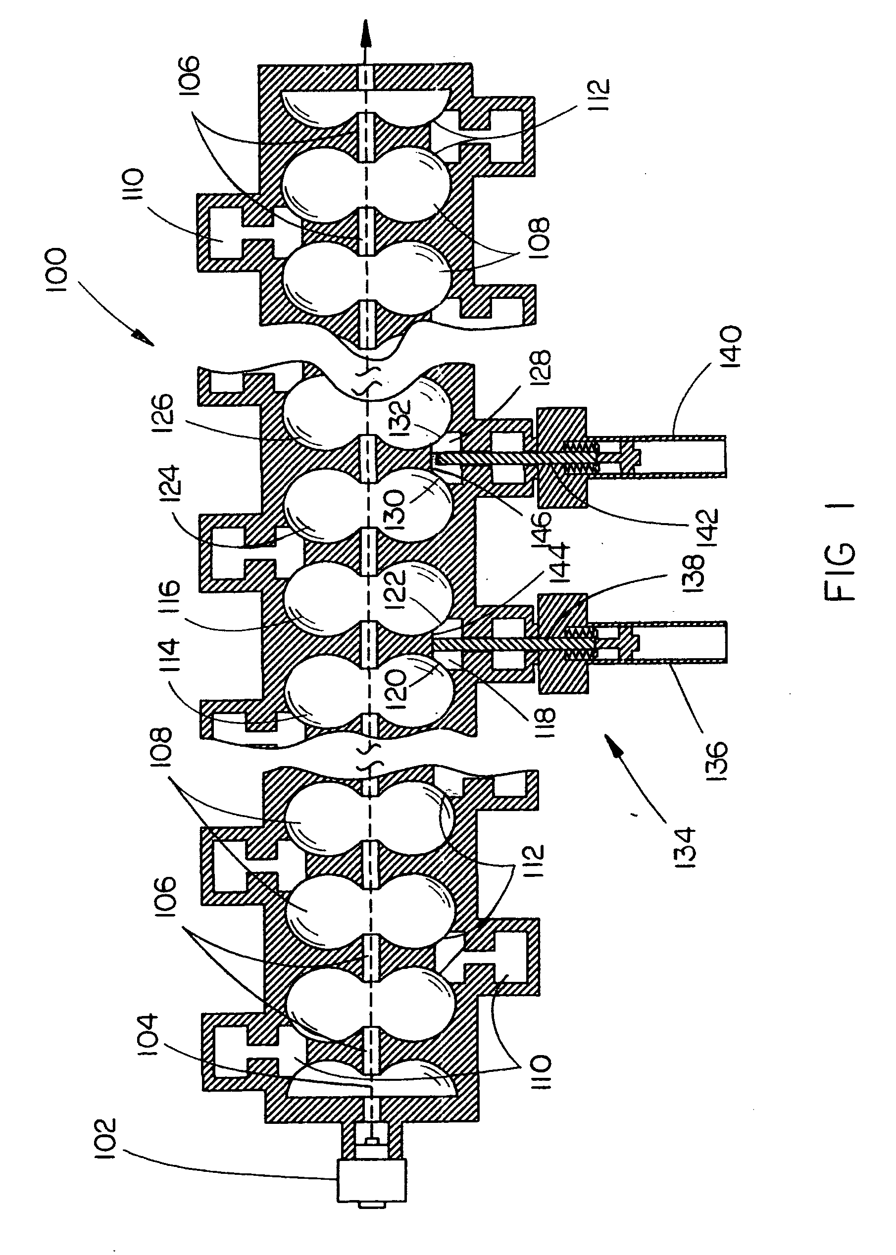
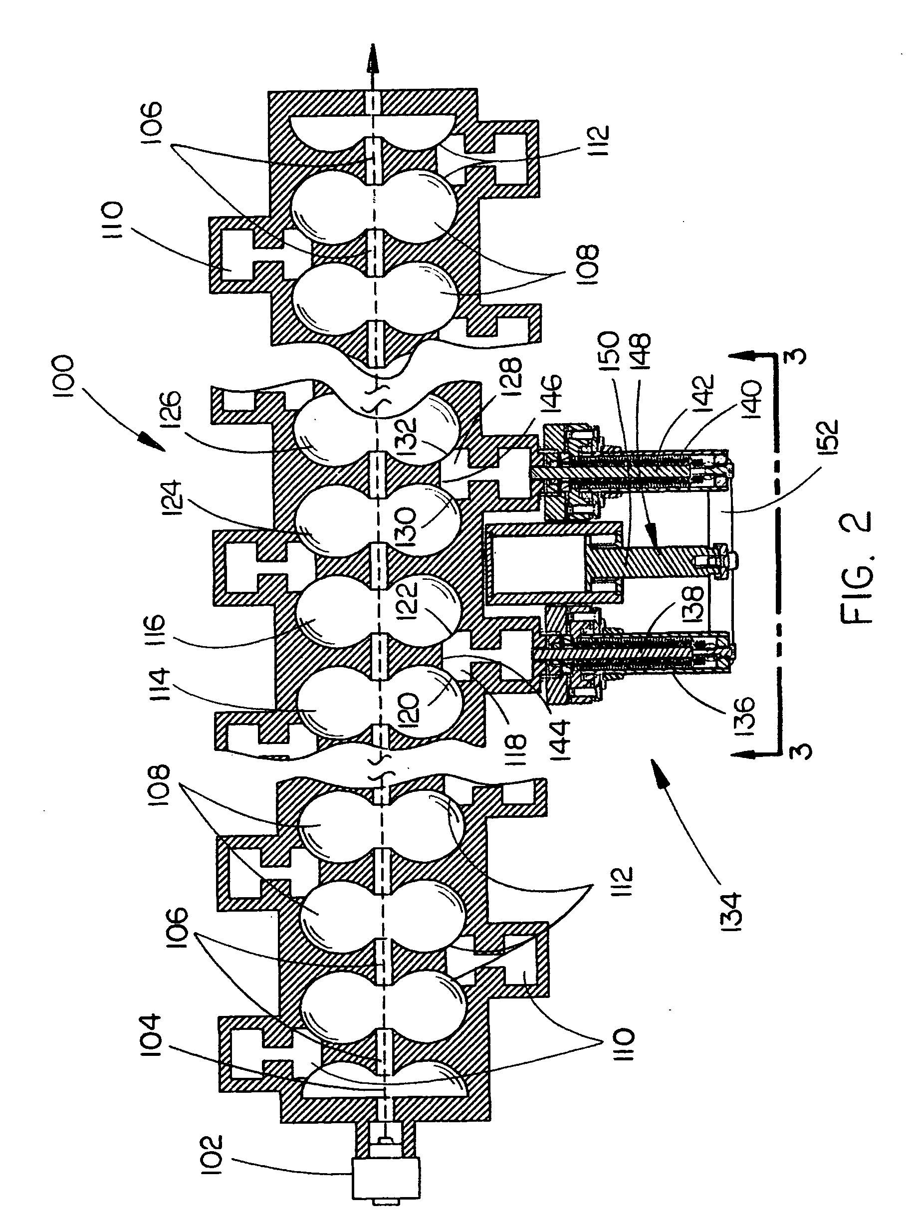
[0025] Referring generally to FIGS. 1 through 14, a standing wave linear particle beam accelerator 100 is described in accordance with exemplary embodiments of the present invention. The standing wave linear accelerator 100 includes a particle beam source for emitting a stream of charged particles, such as an electron beam source 102 for emitting an electron beam 104, or the like. The electron beam 104 is directed longitudinally through the linear accelerator 100, traversing a passage 106 defined through a series of electromagnetically coupled accelerating cavities 108. The accelerating cavities 108 have approximately the same resonant frequency and are electromagnetically coupled with side cavities 110 through irises 112. In embodiments, adjacent accelerating cavities 108 are electromagnetically coupled with a common si...


PUM


Abstract

A dual-plunger energy switch assembly for standing wave linear particle beam accelerators capable of operating in a higher energy mode and a lower energy mode employs two mechanical plungers that can be extended different distances inside two side cavities of the linear accelerator. When the linear accelerator is operated in the higher energy mode, both plungers are retracted out of the side cavities. To achieve high output while the linear accelerator is operated in the lower energy mode, the two plungers are radially inserted into the two side cavities to adjust the electromagnetic accelerating field along the length of the accelerator, e.g., one plunger is inserted into a side cavity so that the plunger touches the smile surface of the side cavity, while the second plunger is inserted into a second side cavity so that the plunger is adjacent to, but not touching, the smile surface of the side cavity.

Description

BACKGROUND OF THE INVENTION [0001] The present invention relates generally to the field of standing wave linear particle beam accelerators, and more particularly to an energy switch assembly for a standing wave linear particle beam accelerator having two mechanical plungers, which, when radially inserted into two side cells or cavities of the linear particle beam accelerator, increases the output of the linear accelerator at lower energies. [0002] Medical linear particle beam accelerators that operate at two or more energies suffer from the fundamental limitation that the internal structure cannot be optimized for multiple energies. Because the length of the accelerating structure is fixed, in order to produce both high energy and low energy beams, the cavities are operated at maximum electric field gradient in the higher energy mode and lower gradient in the lower energy mode. The lower gradient causes more electrons to be lost as they travel through the structure, resulting in los...

Claims


Application Information

Patent Timeline
Patent Type & Authority Applications(United States)
IPC IPC(8): H05H9/00
CPCH05H9/04H05H7/18
Inventor HO, CHING-HUNGOSHATZ, DARYL
Owner SIEMENS MEDICAL SOLUTIONS USA INC
Why Eureka
Try Eureka