

Backup battery assembly for electronic device
- Summary
- Abstract
- Description
- Claims
- Application Information
AI Technical Summary
Benefits of technology
Problems solved by technology
Method used
Image

Examples
Embodiment Construction
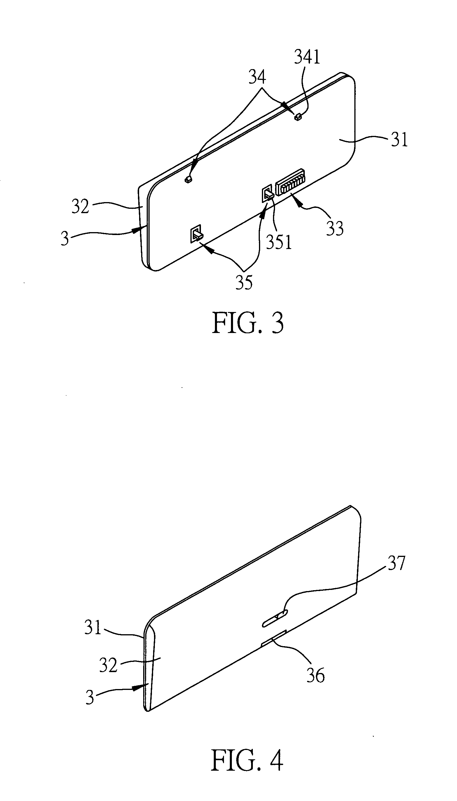
[0031] As shown in FIGS. 3, 4 and 5, the present invention proposes a backup battery assembly for an electronic device. The backup battery assembly comprises a battery body 3; and an electric connector 33, at least one positioning fastener 34, at least one movable fastener 35, an adjusting member 36 and a locking member 37 that are mounted on the battery body 3. The battery body 3 comprises a first surface 31 and an opposed second surface 32, wherein the first surface 31 is slanted with respect to the second surface 32, making the battery body 3 substantially have a wedge shape. It should be noted that the arrangement is not limited to having the first surface 31 slanted with respect to the second surface 32 as in this embodiment, the first surface 31 and the second surface 32 of the battery body 3 may further intersect to similarly make the battery body 3 substantially wedge-shaped.
[0032] The positioning fastener 34 is mounted on the first surface 31 of the battery body 3. The mov...
PUM
 Abstract
Description
Claims
Application Information