Multistage motor-compressor for the compression of a fluid

Inactive Publication Date: 2007-02-15
CENT RECERCHE FIAT S PA
View PDF4 Cites 78 Cited by
  • Summary
  • Abstract
  • Description
  • Claims
  • Application Information

AI Technical Summary

Benefits of technology

[0008] The object of the disclosure is that of embodying a two-stage motor-compressor, which is highly

Problems solved by technology

In the case where the second section is axial, the fluid flow entering the conveyor undergoes abrupt changes of direction, giving rise to a drop in flow pressure, high operational power consumption and reduced efficiency for the motor-compre

Method used


Image

  • Multistage motor-compressor for the compression of a fluid
  • Multistage motor-compressor for the compression of a fluid
  • Multistage motor-compressor for the compression of a fluid

Examples


Example

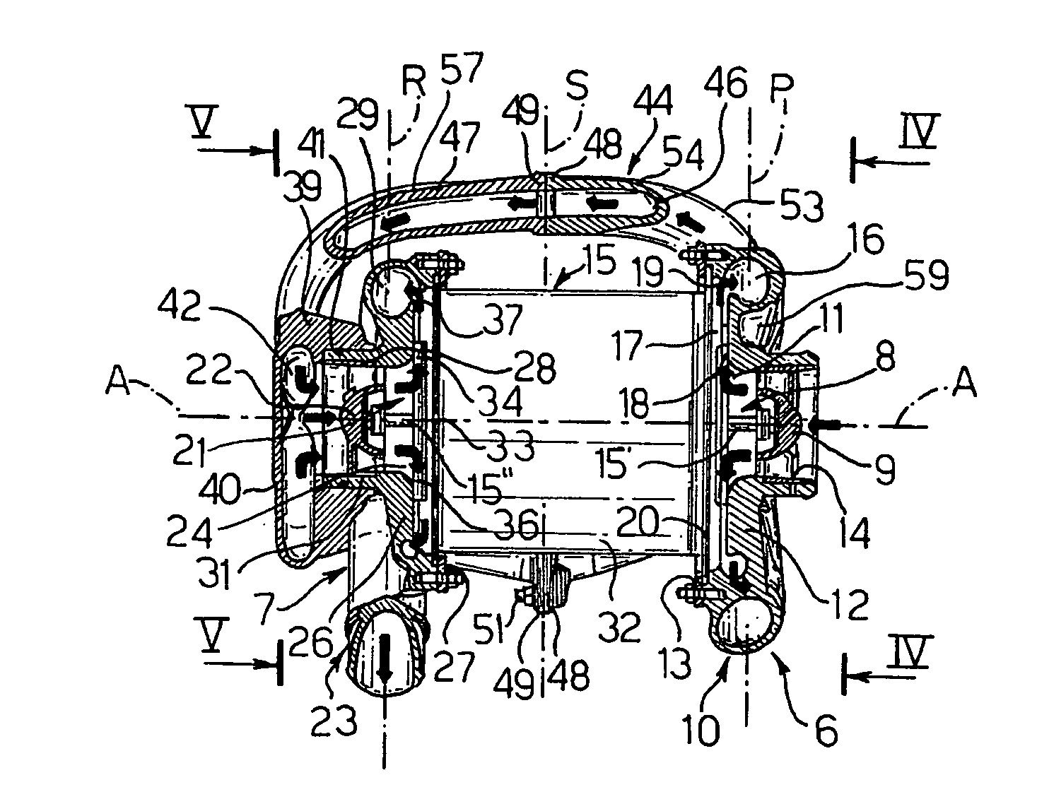
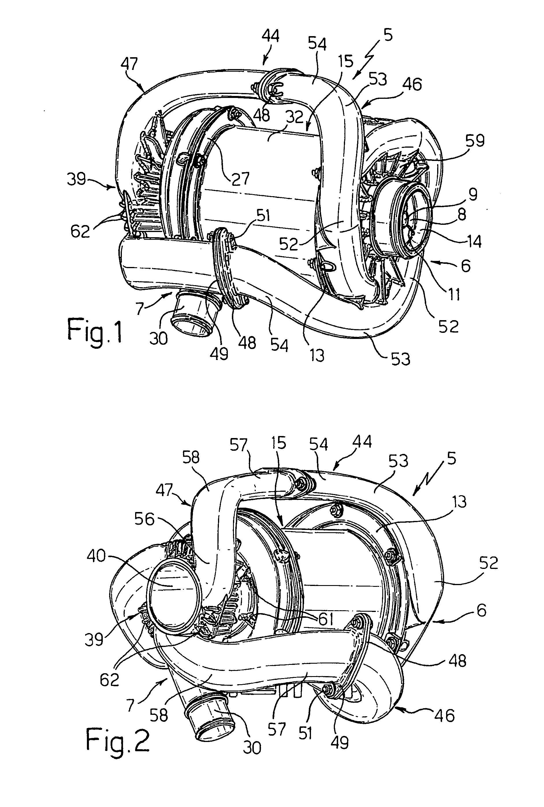
[0022] With reference to FIGS. 1 and 2, reference 5 generically indicates a multistage motor-compressor for the compression of a fluid, for motor vehicles for example. In particular, the motor-compressor 5 is of the type with two stages 6 and 7, low pressure and high pressure respectively, and is suitable for the supply of pressurized air in a fuel cell system or for supplying air to internal combustion engines, or for any system in which compressed air is required.

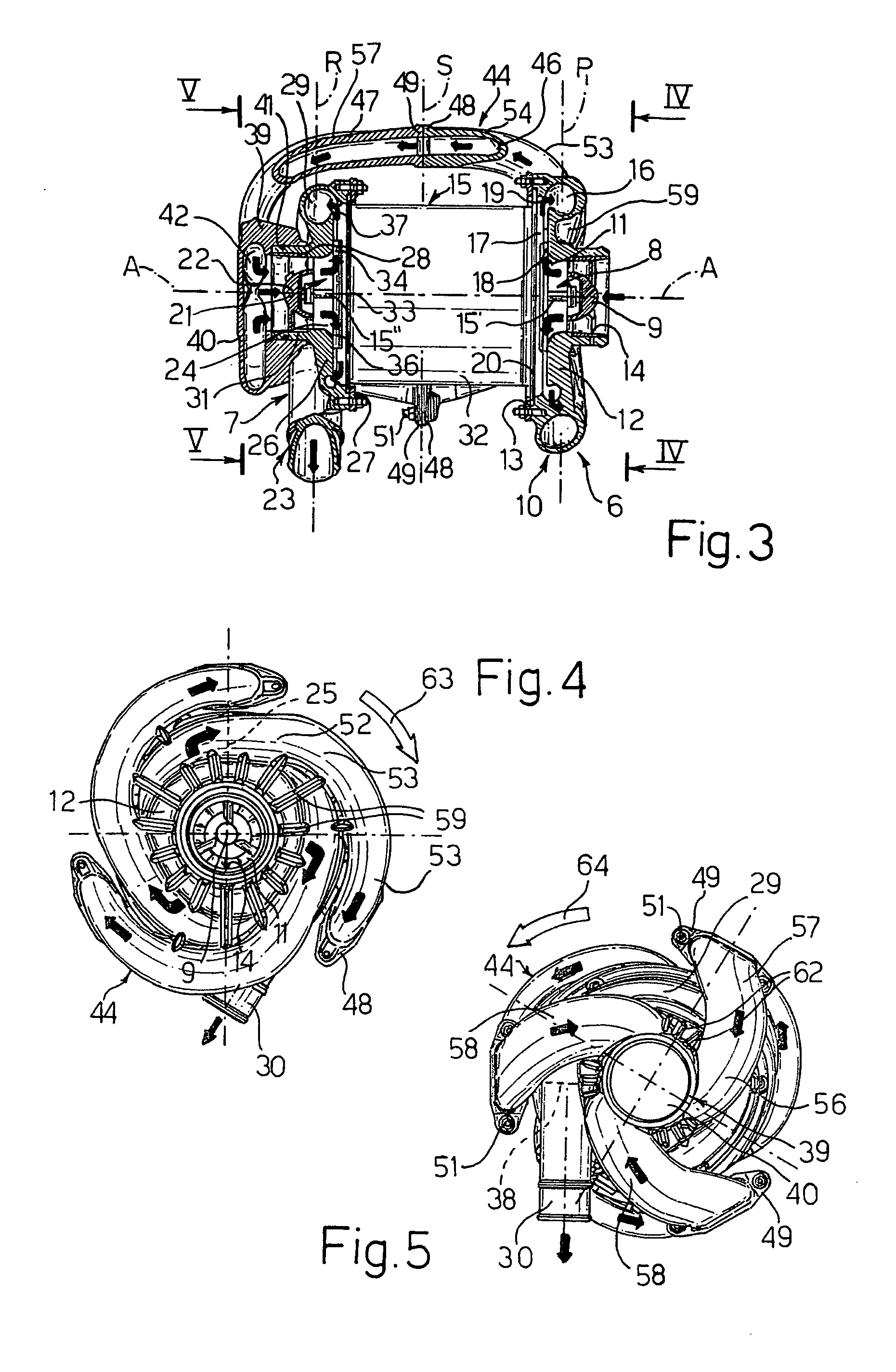
[0023] The low-pressure stage 6 comprises a low-pressure impeller, which henceforth will be called the primary impeller 8 (FIG. 3). The primary impeller 8 rotates around an axis A and is preceded by a fixed ogival portion 9, placed inside a low-pressure scroll, which henceforth will be called the primary scroll 10. The primary impeller 8 is fixed on one end 15′ of a shaft of an electric motor 15. The primary impeller 8 also comprises a series of substantially radial, shaped blades 11, of known type.

[0024] The primary sc...


PUM


Abstract

A motor-compressor is provided that includes a first compression stage with a primary impeller and at least one delivery duct, a second compression stage with a secondary impeller spinning in a predetermined direction of rotation, and at least one transfer duct placed so as to put the delivery duct in communication with a fluid conveyor for the second stage. The transfer duct is shaped in a way to create a fluid flow entering the conveyor with a substantially helical course and a direction of rotation opposite to the direction of rotation of the secondary impeller.

Description

CROSS REFERENCE TO RELATED APPLICATIONS [0001] This application claims benefit under 35 U.S.C. §119(a) of Italian Patent Application No. T)2005A 000558, filed Aug. 5, 2005 and European Patent Application No. 06101557.4, filed Feb. 10, 2006, the entire contents of both of which are incorporated herein by reference. BACKGROUND OF THE INVENTION [0002] 1. Field of the Invention [0003] This disclosure refers to a multistage motor-compressor for the compression of a fluid, for motor vehicles for example. In particular, the disclosure refers to a two-stage motor-compressor for the supply of pressurized air to fuel cell systems. [0004] 2. Description of Related Art [0005] Motor-compressors of the above-stated type are well known, in which the first-stage scroll is connected to a tangential first section of a transfer duct, while a second axial or radial section of the transfer duct is connected to a fluid conveyor for the second-stage scroll. In the case where the second section is axial, t...

Claims


Application Information

Patent Timeline
IPC IPC(8): F04B17/00
CPCF04D17/12F04D29/441F04D25/06
Inventor PESOLA, FABIOMARCHESE, PAOLOCAENAZZO, DARIO
Owner CENT RECERCHE FIAT S PA
Why Eureka
Try Eureka