
Electric drive apparatus

a technology of electric motors and drive shafts, applied in electrical devices, dynamo-electric machines, toothed gearings, etc., can solve the problems of unloading the geared motor assembly with the plural electric motors, and small torque output, etc., to achieve compact and evenly loaded torque output, the effect of large torque outpu

Inactive Publication Date: 2007-02-15
SUMITOMO SHI DEMAG PLASTICS MACHINERY
View PDF9 Cites 6 Cited by
  • Summary
  • Abstract
  • Description
  • Claims
  • Application Information

AI Technical Summary

Benefits of technology

The present invention provides an electric drive apparatus with multiple electric motors that can operate at different speeds or speed ratios. The driven shafts are connected to the motors through separate gear mechanisms, which allows for separate control of each shaft. The gear mechanisms are interposed between the motors and the rotor, and can be designed with different gear ratios to optimize torque output and minimize misalignment between the shafts. The electric drive apparatus is compact, requires minimal installation space, and is efficient and generates little noise during operation. The invention also includes a hollow-shaft drive and a plurality of electric motors disposed in symmetric relationship to a center axis. These features make the electric drive apparatus ideal for use in various applications such as injection molding machines and extruders.

Problems solved by technology

A drawback of this construction is the uneven load the geared motor assembly with the plural electric motors is subjected to because the electric motors are operated differently and independently from one another.
Moreover, only a small torque output can be generated since the driven shafts are not individually acted upon by all electric motors.

Method used


Image

  • Electric drive apparatus
  • Electric drive apparatus
  • Electric drive apparatus

Examples


Embodiment Construction

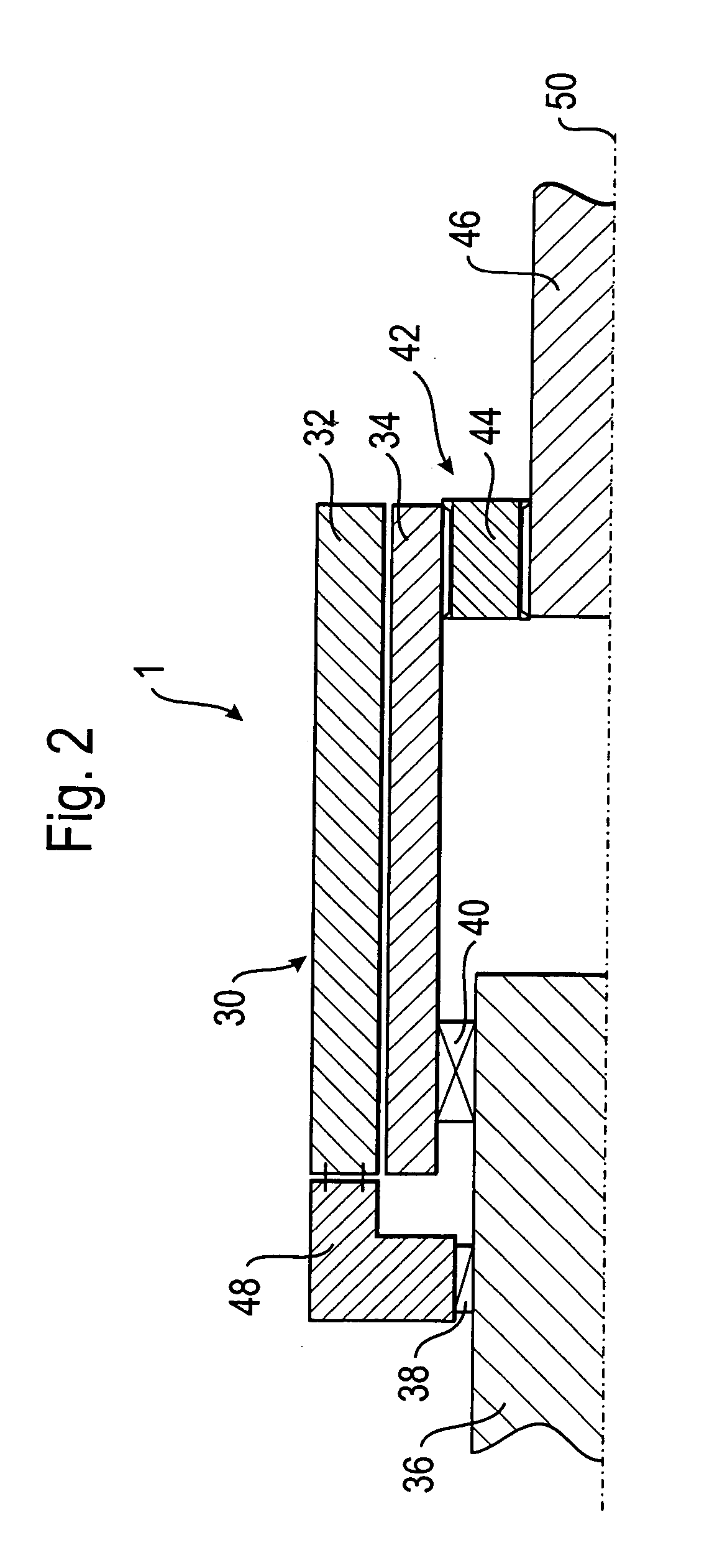
[0029] Throughout all the Figures, same or corresponding elements are generally indicated by same reference numerals. These depicted embodiments are to be understood as illustrative of the invention and not as limiting in any way. It should also be understood that the drawings are not necessarily to scale and that the embodiments are sometimes illustrated by graphic symbols, phantom lines, diagrammatic representations and fragmentary views. In certain instances, details which are not necessary for an understanding of the present invention or which render other details difficult to perceive may have been omitted.

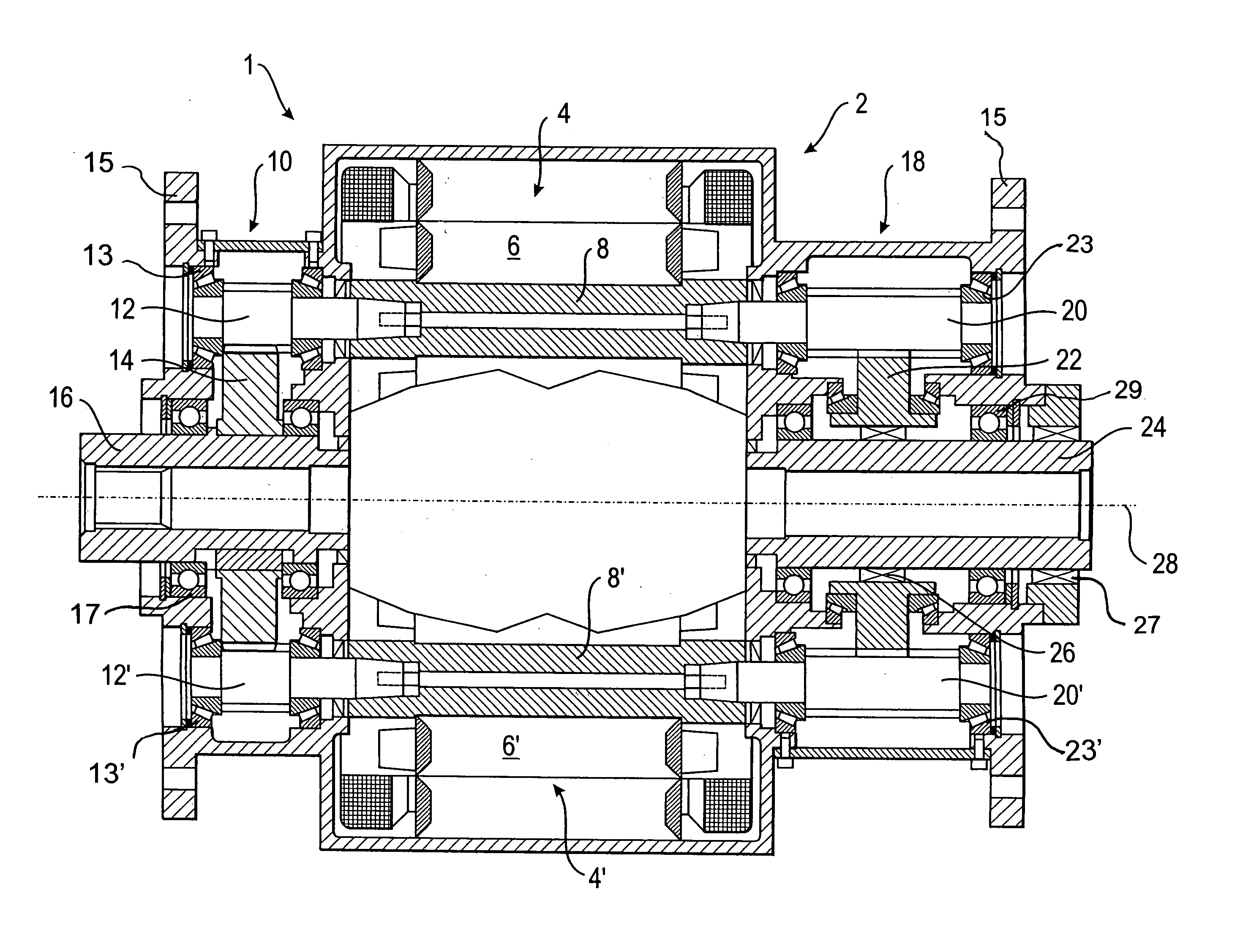
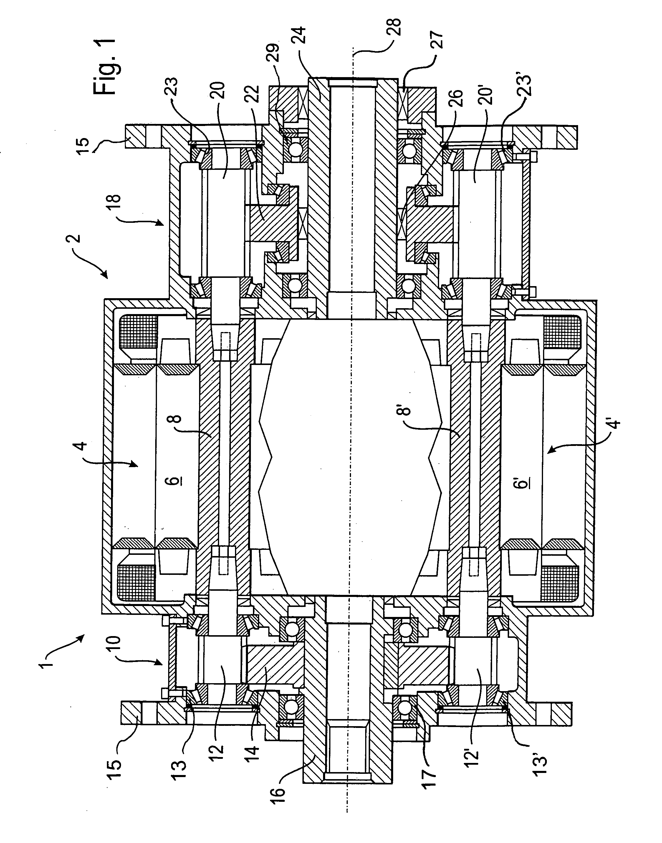
[0030] Turning now to the drawing, and in particular to FIG. 1, there is shown a longitudinal section of one embodiment of an electric drive apparatus according to the present invention, generally designated by reference numeral 1. The drive apparatus 1 defines a longitudinal center axis 28 and includes a compact drive 2 constructed along the center axis 28 and having electr...


PUM


Abstract

An electric drive apparatus includes at least one electric motor having a rotor and at least two driven shafts which are disposed in coaxial relationship and driven at different rotation speed during operation of the electric motor. The driven shafts are constructed for separate connection to the rotor. Interposed between the rotor and at least one of the driven shafts is a gear mechanism in the absence of any direct interaction of the gear mechanism with the other one of the driven shafts.

Description

CROSS-REFERENCES TO RELATED APPLICATIONS [0001] This application claims the priority of German Patent Application, Serial No. 10 2005 023 032.6, filed May 13, 2005, pursuant to 35 U.S.C. 119(a)-(d), the content of which is incorporated herein by reference. BACKGROUND OF THE INVENTION [0002] The present invention relates, in general, to an electric drive apparatus. [0003] Nothing in the following discussion of the state of the art is to be construed as an admission of prior art. [0004] U.S. Pat. No. 5,463,914, issued on Nov. 7, 1995, discloses a multi-function power transmission mechanism having a plurality of miniature motors drawing little power. The motors are assembled together into a motor assembly to generate a relative large torque output, using a down-speed gear set, for application in electric appliances. [0005] European Pat. Appl. No. EP 1 319 866 A1 describes a geared motor which includes a plurality of electric motors, each having an output shaft connected to a driving pi...

Claims


Application Information

Patent Timeline
Patent Type & Authority Applications(United States)
IPC IPC(8): F16H3/72
CPCH02K16/00H02K7/116
Inventor WESSELY, RALPH
Owner SUMITOMO SHI DEMAG PLASTICS MACHINERY
Learn More