Wearable human physiological and environmental data sensors and reporting system therefor

a wearable, human body technology, applied in the field of wearable human physiological and environmental data sensors, can solve the problems of limited monitoring, severely restricting the flexibility and motion of users, etc., and achieve the effect of minimizing interference with human motion and flexibility, minimizing interference with human flexion and motion, and reducing the movement and flexibility of the body

Inactive Publication Date: 2007-02-15
J FITNESS LLC
View PDF100 Cites 118 Cited by
  • Summary
  • Abstract
  • Description
  • Claims
  • Application Information

AI Technical Summary

Benefits of technology

[0014] An apparatus is disclosed which is adapted to specifically provide the ability to mount both sensors and computing apparatus on the human body while maintaining said sensors and apparatus within a proximity zone of the body such that the mobility and flexibility of the body are not deleteriously affected by the presence of the apparatus. The device is primarily comprised of a series of pads having rigid and flexible sections within which the sensors and computing apparatus may be housed. These pods are typically comprised of a rigid material having a minimum hardness or rigidity mounted in conjunction with certain more flexible sections to allow relative movement of the rigid material sections with respect to each other. The flexible material is further utilized to conform said rigid sections to certain pre-specified portions of the human body although it is to be specifically noted that under certain circumstances, the entire pod embodiment can be constructed of the flexible material. The pods are particularly sized and shaped to minimize interference with human motion and flexibility, and are mounted in certain distinct, pre-selected locations on the human body corresponding to the pre-specified shapes. It is to be specifically noted that each of the shapes disclosed herein comprises a maximum size and shape for each particular location. In any specific application, the minimization of the size and shape of any sensor or computing apparatus together with its rigid housing would be considered desirable to minimize interference with human flexion and motion.
[0037] 3. Areas that maximize available surface area or minimize surface irregularities.
[0039] With respect to the form of the various proximity spaces in the containment pods placed therein, a core concept includes forming a concavity on the inside surface of the material to accept a generally convex exterior surface of the human body. Exterior surfaces of the pods are generally convex to deflect objects and avoid bumps and snags. Furthermore, tapering and radiusing of the sides, edges and corners creates safe, soft and stable forms. In certain circumstances, chamfering and scalloping of surfaces are utilized to minimize specific interaction with proximate body parts or physical objects and facilitate extended contact upon motion.

Problems solved by technology

In the many applications, however, monitoring is limited to these short periods of time by limitations associated with the monitoring devices and the sensors themselves.
A significant shortcoming of the prior art devices, however, is that while they provide a lightweight and mobile computing or monitoring platform, they nevertheless severely restrict the flexibility and motion of the user.
None of the prior art references disclose a specific location or series of locations proximate to the human body which would minimize or eliminate the interference of the body-mounted computer or sensor mechanism with normal or athletic bodily function and flexibility.
What is lacking in the art, therefore, is a sensor array and computing apparatus which is wearable on the human body in such a manner and placement that the user's motion and flexibility are not compromised.

Method used


Image

  • Wearable human physiological and environmental data sensors and reporting system therefor
  • Wearable human physiological and environmental data sensors and reporting system therefor
  • Wearable human physiological and environmental data sensors and reporting system therefor

Examples


embodiment 10

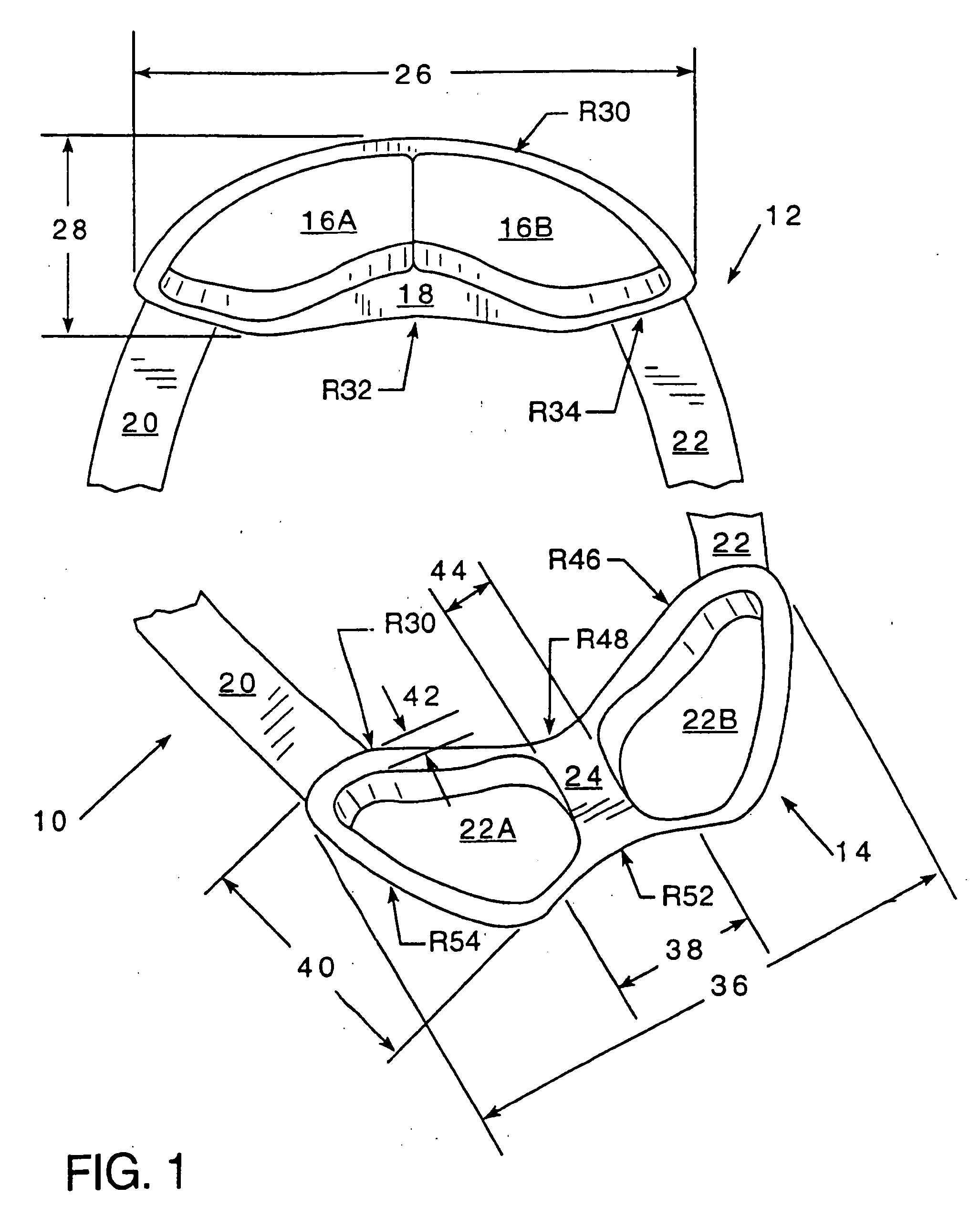
[0071] Referring now to FIG. 1, the collar or neck embodiment of a pod set is illustrated. This set preferably comprises four pods, 16A, 16B, 22A and 22B, mounted within a flexible collar. The flexible collar may be of a unitary construction or comprised of front section 18, rear section 24, and connecting sections 20 and 22. Either or both connecting sections 20 or 22 may be of unitary construction and stretchable to the point that the head may be inserted therebetween or may be connected through a well known fastening means. The collar in embodiment 10 has a front section 12, which is primarily comprised of collar front flexible section 18 having a length 26 of 7.89 inches and a width 28 of 2.82 inches. The front edge of section 12 has a radius R30 of 4.42 and a rear radius R32 of 6.3. Rigid pods16A and 16B are mounted thereon with a flexible space deposed therebetween. While pod 16A and 16B may abut each other, a space of at least ⅜ inch is preferably disposed therebetween. The f...

embodiment 152

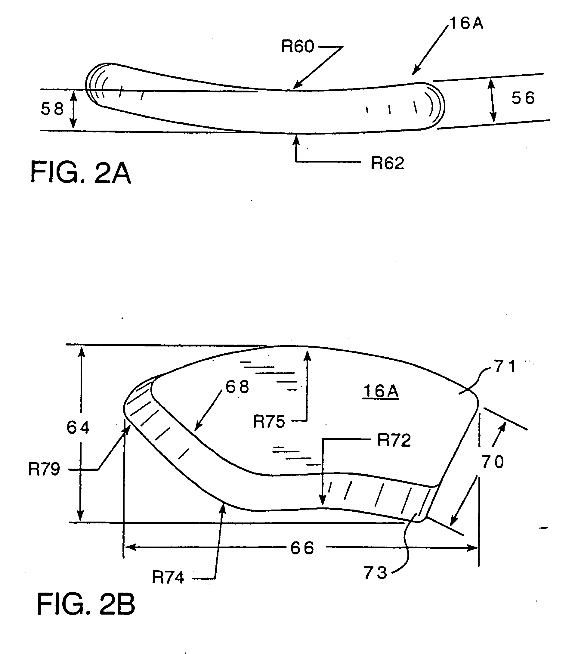
[0078] Referring now to FIG. 7, and with general references to FIG. 6, FIG. 7A shows pod 154A being the analogue of pod 154 for the rightmost section of the upper torso embodiment 152 having an overall height 196 of 5.01 inches and an overall width 198 of 2.66 inches. Pod 154A may generally be described as having three major areas, top and bottom convex sections 164 and a central concave section 166, forming a portion of the chamfer described earlier. The topmost convex section has a centerpoint length of 0.79 inches and the topmost curve R204 is provided with a radius of 0.88 inches. Radius R204 transitions leftwardly to radius 216 of 3.75 inches and rightwardly to concave radius R206 being 5.48 inches. A distance 202 of 1.74 inches is taken from the mid-point of the transitional curve between R206 and R204 to the topmost point of 154A. Radius R206 traverses downwardly and transitions to second concave radius R208 having a dimension of 3.68 inches, finally transitioning into bottom...

embodiment 560

[0087] Referring now to FIG. 15, a forearm embodiment 560 is shown. Not illustrated but well understood to those skilled in the art, is a flexible cuff which envelops the wrist area having a typical length dimension of 4 inches into which the pod 560 is mounted. The pod for the forearm sits aside of the head of the ulna behind the wrist joint and on top of the tendons. The straightest edge of this roughly circular form follows the line from the tendon extending back from the forefinger. The flexible cuff that surrounds pod 560 encircles the arm and may be curved to avoid interference with the head of the ulna. The cuff could also extend the length of the forearm, curving under the bicipital fascia and wrapping upwardly along the line defined by the brachialis muscle. The small size and low profile of pod 560 are specifically intended to allow complex skeletal twisting and to permit the forearm to interact with the environment to enter various spaces on or around the body. Pod 560 is...


PUM


Abstract

A method and apparatus is provided to detect the physiological and environmental status of an individual. The apparatus comprises a pod which is worn within a proximity zone of the body such that the mobility and flexibility of the body are not deleteriously affected by the presence of the apparatus. The system permits the dynamic monitoring of human physiological and environmental status data without substantial interference in human motion and flexibility. Sensors and processors are mounted within said pod.

Description

CLAIM OF PRIORITY [0001] This application is a continuation of co-pending U.S. patent application Ser. No. 10 / 313,255 filed Dec. 6, 2002, which is a continuation of U.S. patent application Ser. No. 09 / 419,600 filed Oct. 18, 1999, which issued as U.S. Pat. No. 6,527,711.BACKGROUND OF THE INVENTION [0002] 1. Field of the Invention [0003] The present invention relates to computing hardware and sensor arrays which are suitable for affixation to the human body. More specifically, the invention relates to sensors and computing apparatus which are adapted to detect certain human physiological data along with environmental data and transmit such data, and which are affixed to the human body in such a manner so as not to interfere with normal body flexibility or movement. [0004] 2. Description of the Prior Art [0005] Monitoring of human physiological status data has received a high and growing level of interest in a number of medical, industrial, scientific and recreational disciplines. In c...

Claims


Application Information

Patent Timeline
Patent Type & Authority Applications(United States)
IPC IPC(8): A61B5/00
CPCA61B5/0002Y10S128/905A61B5/0205A61B5/021A61B5/024A61B5/0476A61B5/08A61B5/11A61B5/441A61B5/6804A61B5/6814A61B5/6822A61B5/6824A61B5/6828A61B5/6829A61B5/6831A61B2560/04A61B2560/0462A61B2562/164G01K13/002G06F3/011A61B5/6823Y10S128/92A61B5/01A61B5/7455G01K13/20A61B5/369
Inventor STIVORIC, JOHNGEMPERLE, FRANCINEKASABACH, CHRISTOPHER
Owner J FITNESS LLC
Why Eureka
Try Eureka