Eureka AIR delivers breakthrough ideas for toughest innovation challenges, trusted by R&D personnel around the world.

Needle guard clip with heel

Inactive Publication Date: 2007-02-15
SMITHS MEDICAL ASD INC
View PDF68 Cites 48 Cited by
  • Summary
  • Abstract
  • Description
  • Claims
  • Application Information

AI Technical Summary

Benefits of technology

[0007] In accordance with one of the principles of the present invention, there are provided canting-plate needle guards that have desired improvements and enhancements as compared to prior canted-plate designs. To that end, in one aspect, the needle guard includes a spring member, which may be a leaf spring, extending from the first wall past an edge of the intermediate wall, which may be defined by one or two struts, and into operative engagement with a bearing surface, w

Problems solved by technology

The commercial embodiment is believed to have drawbacks including that its design also imposes significant drag force on the needle shaft, which make it difficult and undesirable to use.
But when the needle shaft is present, flexing of the members is limited such that the holding force is very high.
As a consequence, the duckbill members will remain flexed and will drag or scrape against the catheter hub interior

Method used


Image

  • Needle guard clip with heel
  • Needle guard clip with heel
  • Needle guard clip with heel

Examples


Example

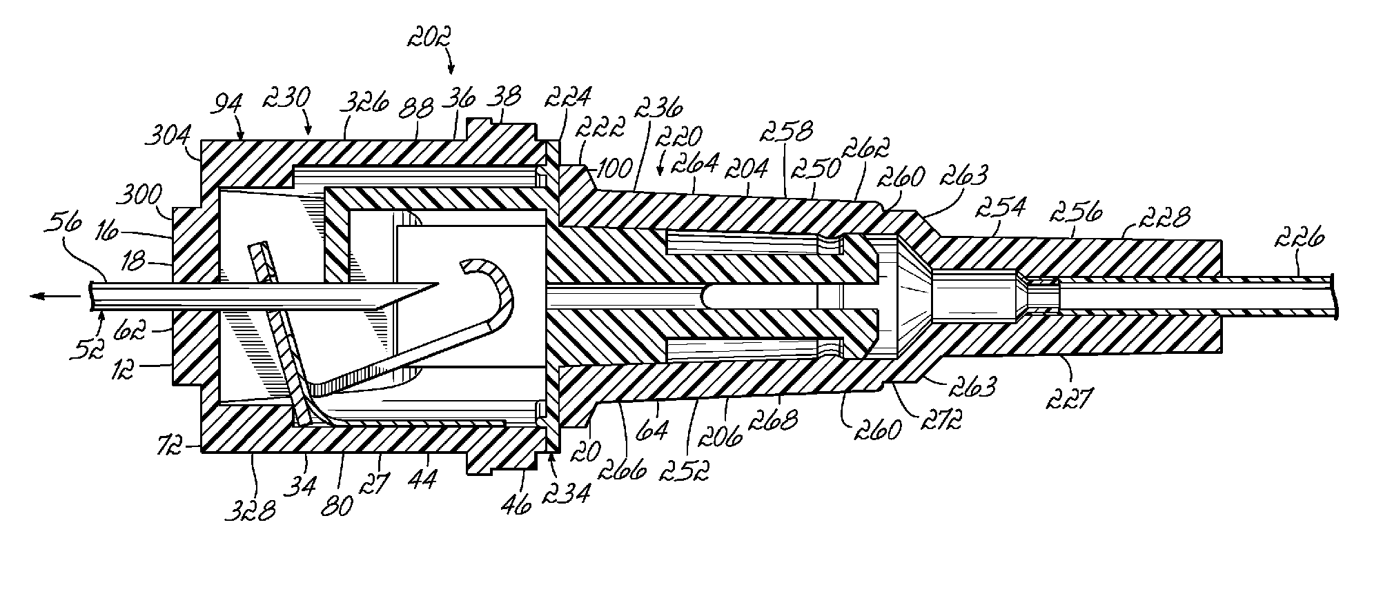
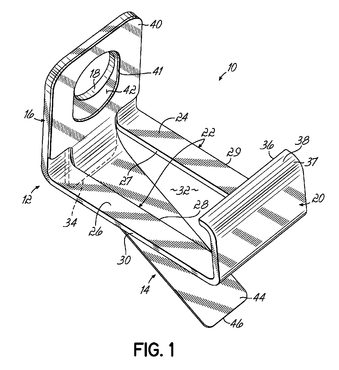
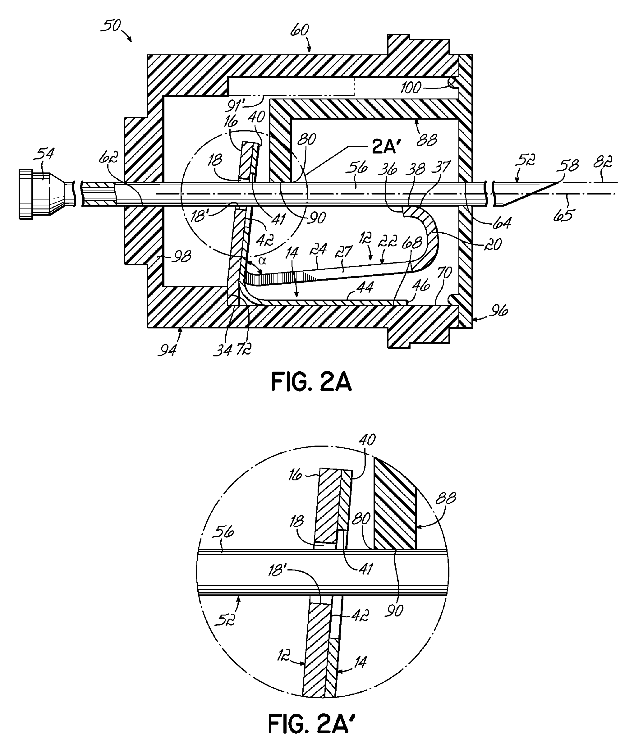
[0031] With reference to FIGS. 2A and 2B, there is shown a second embodiment of a needle guard 50 for a needle 52, such as a hollow hypodermic needle, a hollow or solid catheter insertion needle, or other similar sharp cannulae, attached to and extending from a needle hub 54, which in this embodiment is shown as adapted for a hypodermic needle thus defining a female luer lock attachment but could also or alternatively define a flash chamber. Needle 52 has a needle shaft 56 secured to and extending from needle hub 54 to a distal, sharp tip 58. While not required, the shaft 56 may be of a constant cross-sectional diameter. Needle guard 50 includes a housing 60 having a proximal opening 62 and a distal opening 64 sized to slidably receive the shaft 56 of needle cannula 52 through the housing such that in a first position of needle 52, sharp tip 58 may be distally exposed as shown in FIG. 2A, or in a second position of needle cannula 52, sharp tip 58 is pulled back (by either pulling ne...


PUM


Abstract

A needle guard includes a clip with a canting wall to grip the needle shaft and a distal wall to block the tip thereof, wherein the canting and distal walls may be interconnected by an angled strut, a spring member, such as a leaf spring, may have a portion extending past an edge of the strut to bias the clip to grip the needle shaft, and the distal wall may be or include a stylus and have an L-shape to define a lip to help block the needle tip. The clip may have a depending heel to help pivot the clip about a ledge to grip the needle shaft. A needle support may be provided to limit flexure of the needle which might otherwise allow the needle to come loose from the clip. Arrangements for limiting rotation of the needle hub and needle guard housing are provided, as is a protective shroud to reduce the risk of inadvertent activation of the needle guard. Further, the needle guard may be used with a catheter assembly. Also provided is an improved duckbill release mechanism.

Description

FIELD OF THE INVENTION [0001] The present invention relates to medical needles (such as hypodermic needles, catheter insertion needles or cannulae, or other sharp-tipped hollow or solid cannulae) and, more particularly, to needle guards to protect users and others from the sharp tip of the needle after withdrawal from a patient. DESCRIPTION OF PRIOR ART [0002] A variety of different needle guards have been developed or proposed to protect, i.e., to enclose or otherwise shield, sharp needle tips in recognition of the need to reduce or eliminate accidental needle-sticks. Some needle guards include a housing to enclose essentially the entire needle shaft and needle tip, such as the PROTECTIV Safety I.V. Catheter being marketed by Medex, Inc., the assignee hereof. Others include a clip that moves along the needle shaft to enclose the tip after use, such as shown in U.S. Pat. No. 6,652,486. Still other needle guards provide a housing that moves along the needle shaft with an enclosed act...

Claims


Application Information

Patent Timeline
IPC IPC(8): A61M5/178
CPCA61M5/3273A61M25/0606A61M2005/325A61M2005/3247A61M25/0618A61B17/3496
Inventor ALBERT, SEANJBIALECKI, DENNISM
Owner SMITHS MEDICAL ASD INC
Why Eureka
Eureka Blog
Learn More