Plate making apparatus

Inactive Publication Date: 2007-02-22
FUJIFILM CORP +1
View PDF5 Cites 2 Cited by
  • Summary
  • Abstract
  • Description
  • Claims
  • Application Information

AI Technical Summary

Benefits of technology

[0022] According to the present invention, the plate surface-protecting solution can be selectively ejected to necessary portions on the surface of a printing plate on which an image has been recorded by using the first inkjet head, which enables reduction of the amount of the plate surface-protecting solution used. The amount of the plate surface-protecting solution consumed can be thus reduced and the apparatus can be also downsized.
[0023] According to the present invention, in addition to the effect described above, ejecting the plate surface-protecting solution only to non-image areas can further reduce the amount of the solution used.
[0024] According to the present invention, in addition to the above effect,

Problems solved by technology

However, in the conventional method in which a gum solution is applied onto the surface of a printing plate in which image areas are formed with an applicator of a roller coater type or spray type, or with the gum solution applicator disclosed in JP 5-76768 U, the gum solution is applied onto the whole surface of the printing

Method used


Image

  • Plate making apparatus
  • Plate making apparatus
  • Plate making apparatus

Examples


Example

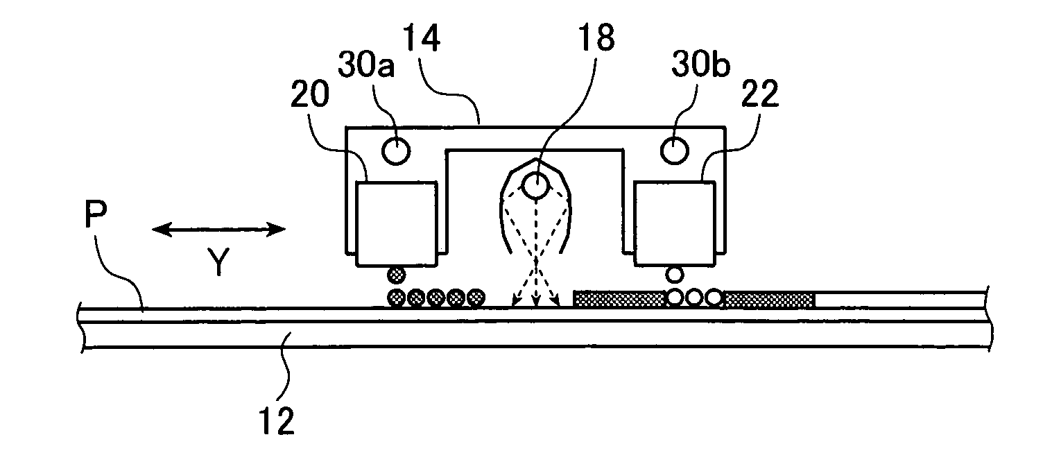
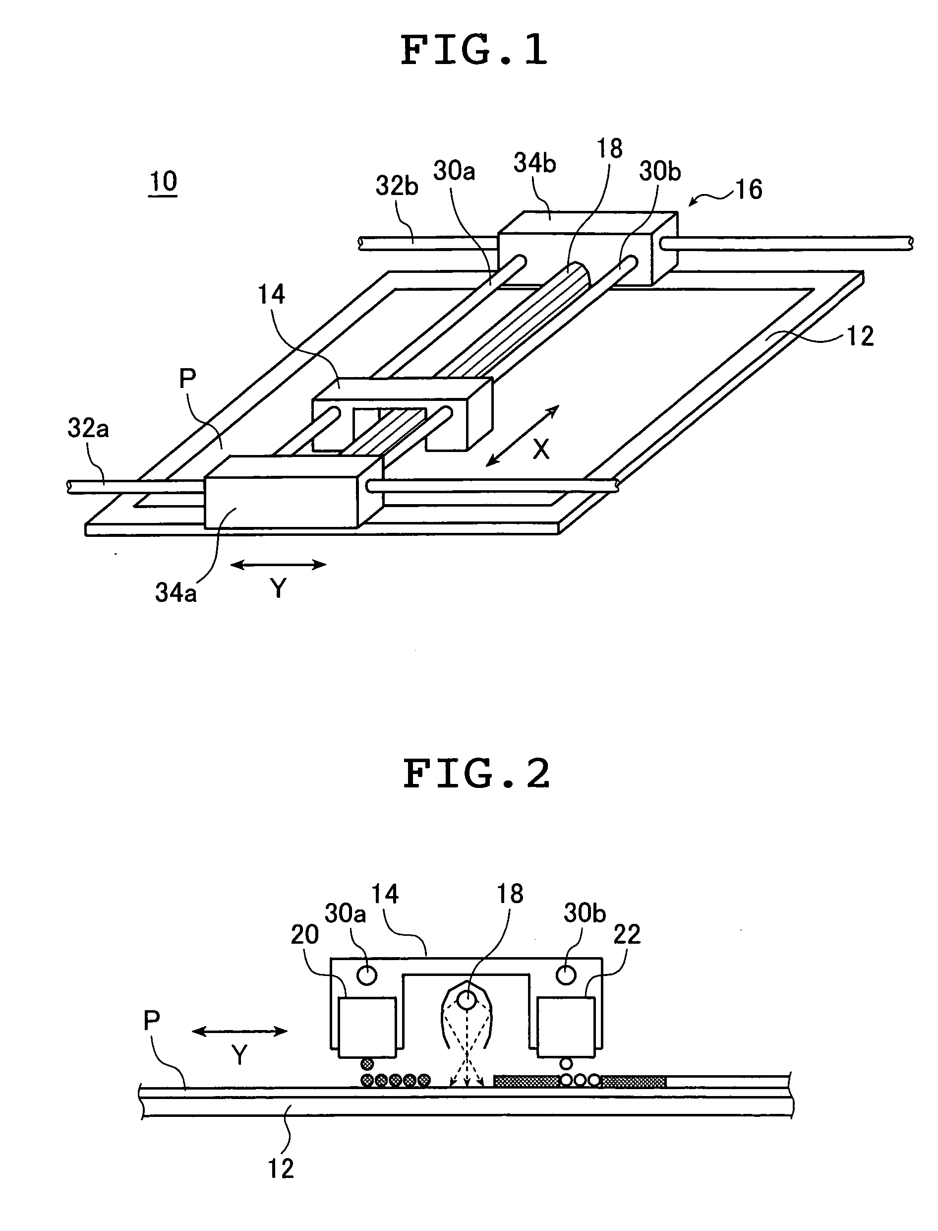
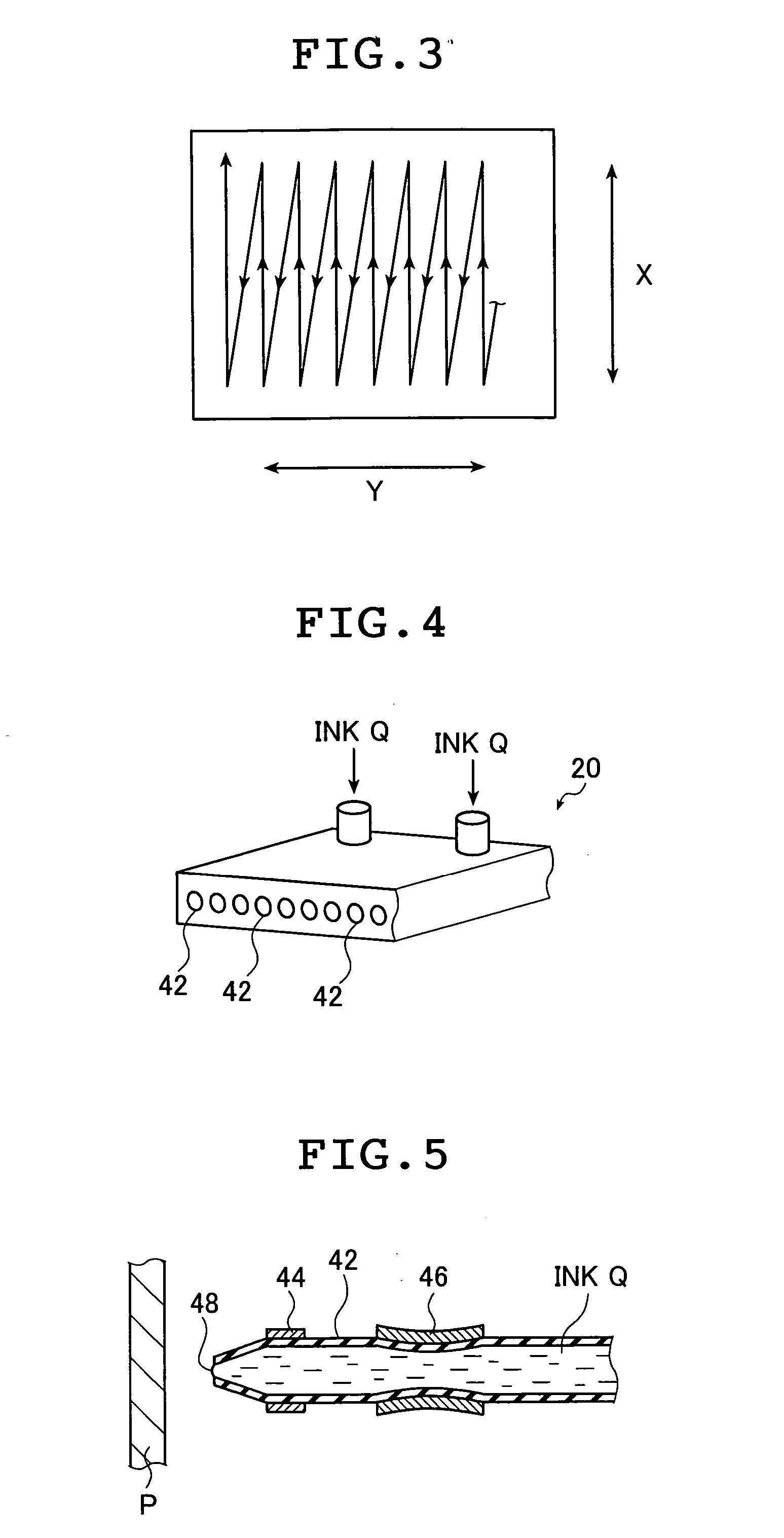
[0031] The plate making apparatus of the present invention is described below in detail with reference to preferred embodiment shown in the accompanying drawings.

[0032] In the present invention, a plate for use in printing is in general collectively referred to as a printing plate. Therefore, for example, one having an image recorded on part or the whole of its surface, in other words, one having image areas and non-image areas formed thereon, one that is ready for use in printing and one whose non-image areas are coated with a plate surface-protecting solution such as gum solution are all called the printing plate. However, when a support having no image formed on its surface, in other words, a support on which image areas and non-image areas are not formed at all, for example, a support such as a metal plate that was merely subjected to surface treatment for manufacturing a printing plate is only to be distinguished from the printing plate described above, this support is particu...


PUM


Abstract

A plate making apparatus makes a printing plate for lithographic printing. The apparatus includes a first inkjet head which ejects selectively a plate surface-protecting solution in response to a first ejection signal onto a printing base plate on which an image has been recorded. The plate making apparatus further includes a drying unit which dries the plate surface-protecting solution ejected selectively onto the printing base plate with the first inkjet head. The apparatus further includes a second inkjet head which ejects an image forming material onto the printing base plate in response to a second ejection signal, and a fixing unit which heats the image forming material ejected onto the printing base plate with the second inkjet head so that the image forming material is fixed as image areas.

Description

[0001] The entire contents of documents cited in this specification are incorporated herein by reference. BACKGROUND OF THE INVENTION [0002] The present invention belongs to a technical field of plate making apparatuses for producing lithographic printing plates. More specifically, the invention relates to a plate making apparatus in which a plate surface-protecting solution is selectively applied onto an image-forming surface of a printing plate on which an image has been recorded (image areas have been formed). [0003] In conventional lithographic printing plates, an image has been recorded (image areas have been formed) on a presensitized plate (a printing base plate on which image areas are not formed) by outputting an original image to a silver halide photographic film in an analog or digital manner through an exposure process to form a film for plate making; exposing a diazo resin or a photopolymerizable photosensitive material (presensitized plate) to light bearing the origina...

Claims


Application Information

Patent Timeline
IPC IPC(8): B41N3/00
CPCB41C1/1066B41J11/002B41J3/543B41J11/00216
Inventor OHISHI, CHIKASHI
Owner FUJIFILM CORP
Why Eureka
Try Eureka