Micromotor structure for hand indicator device

a micromotor and indicator device technology, applied in the direction of identification means, instruments, measurement apparatus components, etc., can solve the problem of increasing the requirement for spa

Inactive Publication Date: 2007-02-22
MICROCOMPONENTS SA
View PDF9 Cites 11 Cited by
  • Summary
  • Abstract
  • Description
  • Claims
  • Application Information

AI Technical Summary

Benefits of technology

[0010] It is an object of the present invention to overcome the aforementioned drawbacks of the prior art by proposing a more compact micromotor structure compared to known micromotors of the prior art. A more compact micromotor allows construction of a more compact hand indicator device and therefore a more compact instrument panel comprising such hand indicator devices or displaying more information than with an instrument panel of the prior art of equivalent size.
[0013] Thus, in the particular non-limiting case according to which the case is fixed to a PCB by the second face, typically via its bottom, there is a free space arranged between a part of the bottom and the PCB. A plurality of electronic components can be arranged in this free space, whereas with the structures of the prior art these components could only be arranged beside the case on the PCB, which consequently increased the requirement for space.
[0017] It is an additional object of the present invention to propose a hand indicator device structure allowing the same hand to be disassembled and remounted on the motor several times without being damaged.
[0018] For this purpose, the indicator device according to the present invention further includes, in a preferred manner, mechanical means for allowing said hand to be disassembled from said shaft a plurality of times. In particular, the hand can be disassembled a plurality of times without the drive shaft or the hand undergoing damage making them unsuitable for use.

Problems solved by technology

A plurality of electronic components can be arranged in this free space, whereas with the structures of the prior art these components could only be arranged beside the case on the PCB, which consequently increased the requirement for space.

Method used


Image

  • Micromotor structure for hand indicator device
  • Micromotor structure for hand indicator device
  • Micromotor structure for hand indicator device

Examples


first embodiment

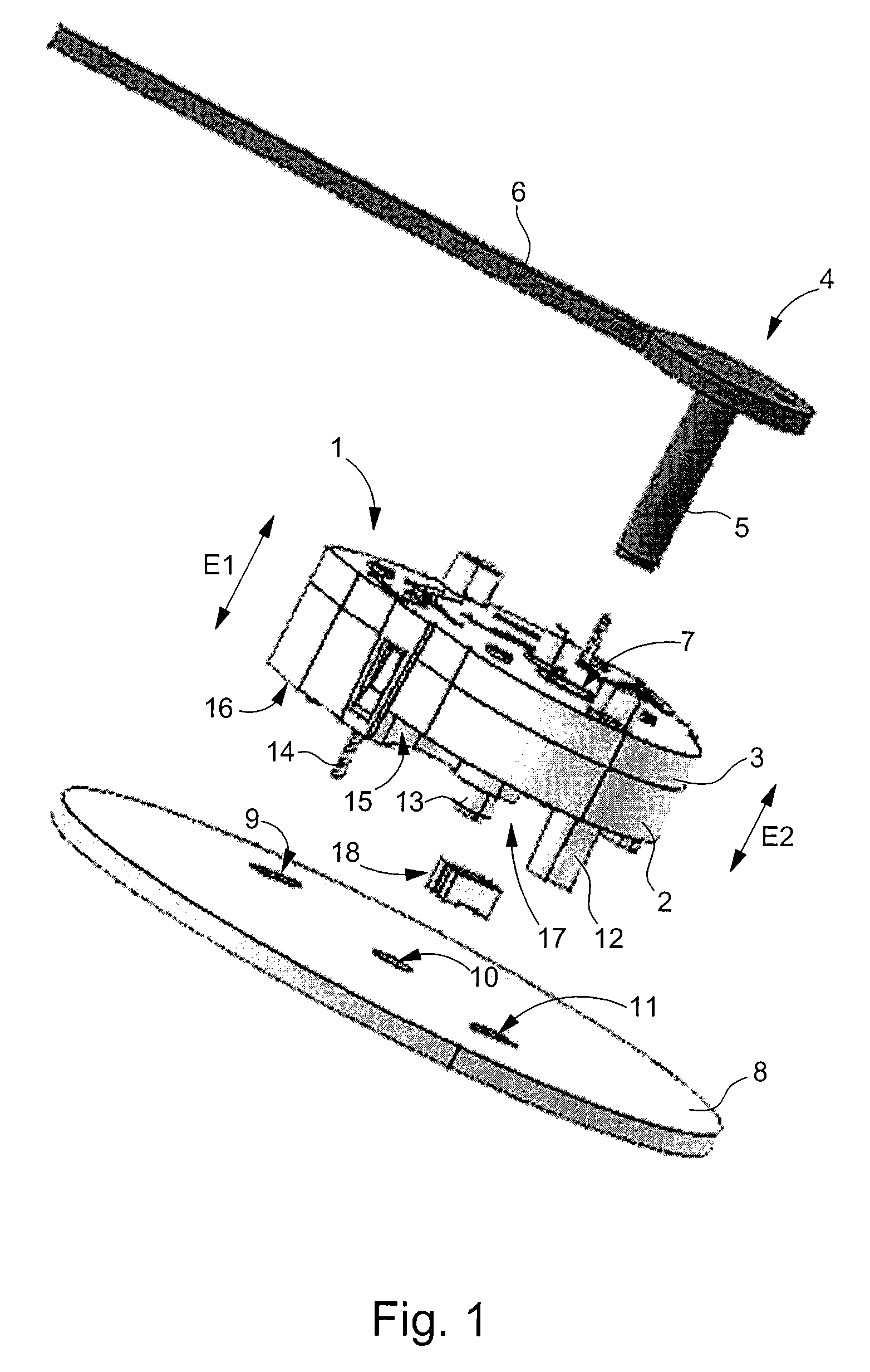
[0026]FIG. 1 shows an exploded perspective view of one part of the indicator hand device for an instrument panel, according to the present invention.

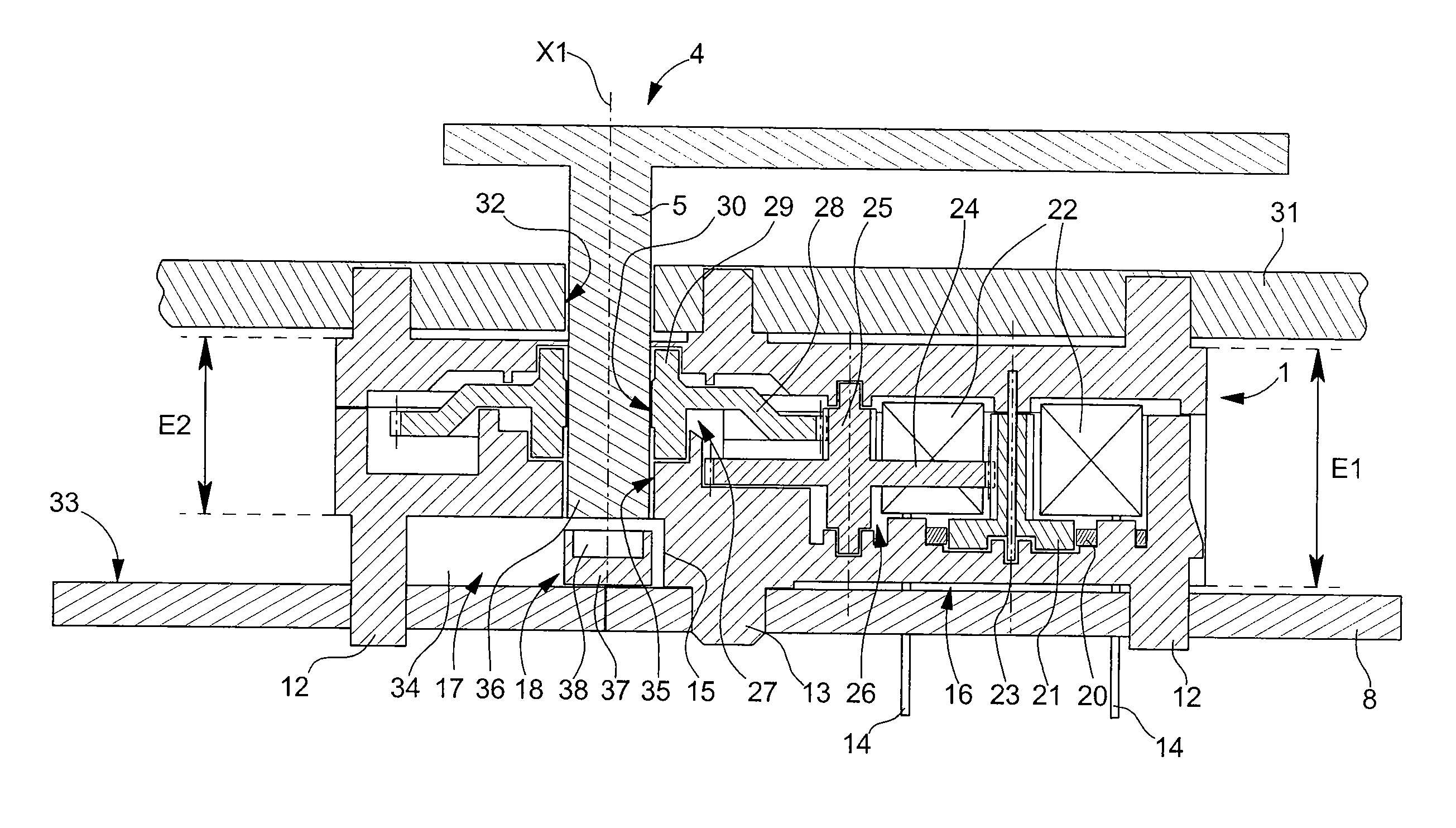
[0027] The device shown in FIG. 1 includes a micromotor 1 comprising a case, composed in particular of a bottom 2 closed by a cover 3 and, inside which are housed various elements (shown in FIG. 2a) for driving an indicator hand 4. Hand 4 includes a stem 5, shown here in cylindrical shape by way of non-limiting illustration, secured to an index 6 whose function is to indicate the value of a measured physical variable opposite indications or scales carried by a dial (visible in FIG. 2a).

[0028] Cover 3 of the case includes in particular an aperture 7 through which the stem 6 of the hand is inserted to secure the latter to a drive wheel set of the micromotor (also visible in FIGS. 2a and 2b). It should be noted that insertion of the hand stem in the drive shaft is carried out after the dial is placed in the micromotor during the instrumen...

second embodiment

[0069] the present invention has been shown in FIG. 3, by way of example. Micromotor arrangements are known wherein the micromotor is fixed to the PCB by its cover and not by its bottom, as shown in FIGS. 1 and 2a. The same reference numerals as those used in relation to the preceding Figures have been used to designate the same elements.

[0070] The arrangement inside the case of micromotor 1 is identical to that described previously. However, according to this embodiment, micromotor 1 is secured to PCB 8 by its cover 3. PCB 8 is also mounted on dial 31 and is further provided with an aperture 40 to leave a passage for indicator hand 4.

[0071] Insofar as, according to this embodiment, the light source cannot be fixed both to the PCB 8 and facing stem 5 of hand 4, an alteration must be provided to its support with respect to the description hereinbefore.

[0072] An extension 41 or support, is provided on the bottom of the case, substantially perpendicular to the bottom for example, to ...


PUM


Abstract

The present invention concerns a micromotor (1) for an indicator device comprising a hand (4) of the type generally used in the instrument panels of motor vehicles. More specifically, the present invention concerns a micromotor (1) of this type comprising a case wherein the thickness E2 of one area is smaller than its maximum thickness E1, so as to form a free space or recess (34) open on the exterior, in particular on the bottom (2) of the case. This recess (34) can be advantageously used for arranging components (18) necessary for the operation of the instrument panel in which the micromotor is mounted, thereby saving space with respect to devices of the prior art.

Description

FIELD OF THE INVENTION [0001] The present invention concerns a micromotor for a hand indicator device comprising a case inside which there are housed motor means and means provided for transmitting the movement from the motor means to a drive shaft with an axis X1 capable of driving a hand indicator. Further, the case comprises a first face, including an aperture making the drive shaft accessible and a second face opposite the first face, the distance separating the first face from the second face defining a maximum thickness E1 of the case. [0002] The present invention also concerns an indictor device for an instrument panel comprising a micromotor, of the type defined hereinbefore, arranged on a printed circuit board, a hand indicator being mounted in the drive shaft of said micromotor. [0003] A common example application of this type of indicator hand device is the indication of variations in a measured variable on the instrument panel of a motor vehicle, such as the speed of mov...

Claims


Application Information

Patent Timeline
Patent Type & Authority Applications(United States)
IPC IPC(8): G01D11/28G12B11/04G01D11/24G01D13/00
CPCG01D11/24G01D13/00G01D11/28G01P1/07
Inventor VUILLIOMENET, MARCPAGES, ALBERTJACOB, GERARDHIRT, ANDREAS
Owner MICROCOMPONENTS SA
Why Eureka
Try Eureka