
High-voltage measuring device

a high-voltage measuring and measuring device technology, applied in the direction of measurement devices, resistance/reactance/impedence, instruments, etc., can solve the problems of high cost and the size of the substrate b>1/b> must be large, and achieve the effect of reducing the size of the substra

Active Publication Date: 2007-02-22
HITACHI ASTEMO LTD
View PDF9 Cites 10 Cited by
  • Summary
  • Abstract
  • Description
  • Claims
  • Application Information

AI Technical Summary

Benefits of technology

[0008] It is an object of the present invention to provide a high-voltage measuring device capable of providing sufficient electric isolation between resistors and between resistors and a voltage measurement circuit without necessity of enlarging a size of a substrate on which the circuit is to be mounted.
[0010] The above-mentioned configuration in which each of the resistive parts has a series circuit of at least one high resistance resistor and at least low resistance resistor results in that the high resistance resistors and low resistance resistors are reduced in size as compared to those in the prior art, and in that an applied voltage excluding a voltage across the voltage measuring circuit is distributed to the high and low resistance resistors in each of the resistive parts. When the high and low resistance resistors are reduced in size, distances between the high resistance resistors, between the low resistance resistors, and between each of the resistors and the voltage measuring device can be reduced more than the conventional device, whereby, the size of the substrate can be reduced.

Problems solved by technology

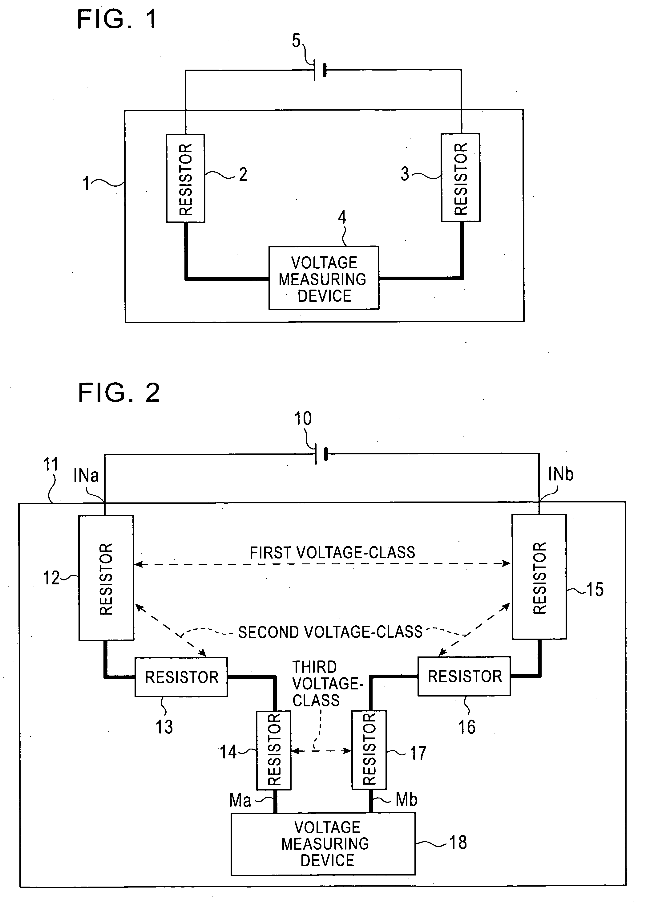
In addition, there arises another problem of high cost that the size of the substrate 1 must be large enough to make sure that the resistances 2 and 3 and the voltage measuring device 4 are separated from each other for electric isolation even under such high electric potential differences between the resistors and between the resistors and the voltage measuring device.

Method used


Image

  • High-voltage measuring device
  • High-voltage measuring device
  • High-voltage measuring device

Examples


Embodiment Construction

[0014] An embodiment of the present invention will be described in detail while referring to the accompanying drawings.

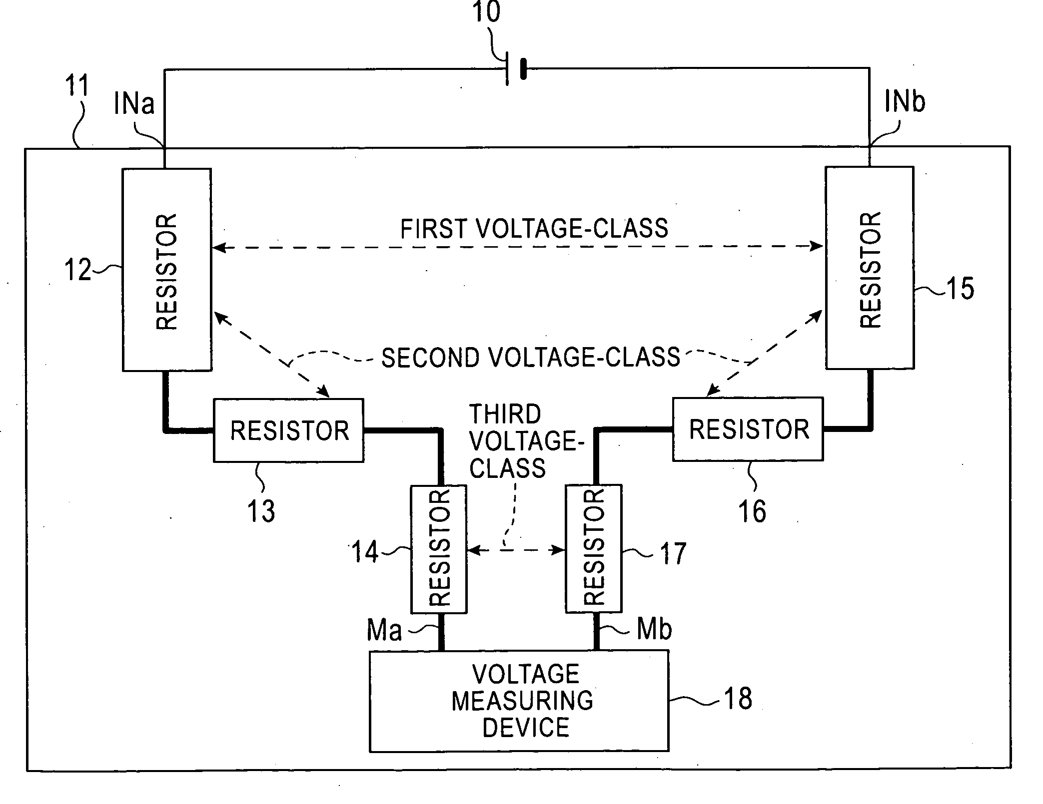
[0015]FIG. 2 shows a high-voltage measuring device according to the present invention. This measuring devices is mounted on a substrate land includes resistors 12-17 and a voltage measuring circuit 18. The resistors 12 and 15 have the same resistance of A Ω as each other. The resistors 13 and 16 have the same resistance of B Ω as each other. The resistors 14 and 17 have the same resistance of C Ω as each other. There are such relations among the resistances that the resistance A is greater in size than the resistance B and the resistance B is greater than the resistance C. There are also such relations among the size of the resistors in appearance that the resistors 12, 15 are greater in size than the resistor 13 and the resistor 16 is greater in size than the resistors 14, 17. The resistors 12, 13, and 14 form one resistor part and the resistors 15, 16, and 17 for...


PUM


Abstract

The present invention provides a high-voltage measuring device capable of providing sufficient electric isolation between resistors and between resistors and a voltage measurement circuit without necessity of enlarging a size of a substrate for carry thereon the circuit. A high-voltage measuring device mounted on a substrate, comprising a high-voltage input terminal pair, a measuring terminal pair, a voltage measuring circuit having input terminals connected to the measuring terminal pair, and two resistive parts. One of the resistive parts electrically connects one of high-voltage input terminal pair and one of measuring terminal pair. The other of resistive parts electrically connects between the other of high-voltage input terminal pair and the other of measuring terminal pair. Each of the resistive parts comprises a series circuit of at least one high resistance resistor and at least one low resistance resistor, wherein a distance between the high resistance resistors in each of the resistive parts is larger than that between the low resistance resistors.

Description

BACKGROUND OF THE INVENTION [0001] 1. Field of the Invention [0002] The present invention relates to a high-voltage measuring device for detecting a high-voltage. [0003] 2. Description of the Related Art [0004] On an accumulator such as a storage battery in an electronic car, a high-voltage measuring device for detecting a high-voltage is provided to protect against the electric overcharge or over-discharge. [0005] As shown in FIG. 1, a conventional high-voltage measuring device is, for example, provided with two resistors 3 and 4 and a voltage measuring circuit 4 which are mounted on a substrate 1, for example, in the form of a printed circuit. Positive and negative terminals of a high-voltage battery 5 are electrically connected to one ends of the resistors 2 and 3, respectively. The other ends of the resistors 2 and 3 are electrically connected to input terminals of the voltage measuring circuit 4, respectively. The resistors 2 and 3 are used for dividing a high-voltage supplied ...

Claims


Application Information

Patent Timeline
Patent Type & Authority Applications(United States)
IPC IPC(8): G01R31/02
CPCG01R15/144
Inventor SUZUKI, KOJITAKEBAYASHI, KENICHIABE, SEIICHIROCHIBA, TAKESHIKATANODA, TOMOYA
Owner HITACHI ASTEMO LTD
Learn More