Scanned probe mounting design

a technology for scanning probes and mounting devices, applied in scanning probe microscopy, measurement devices, instruments, etc., can solve the problems of inability to manipulate a spm cantilever directly without the millimeter-sized substrate, inability to use clips in several measurements, and inability to interfere with electrical measurements, etc., to achieve clean contact, low added mass, and benefit from strength and conductivity

Active Publication Date: 2020-10-27
ANGSTROM SCI
View PDF1 Cites 0 Cited by
  • Summary
  • Abstract
  • Description
  • Claims
  • Application Information

AI Technical Summary

Benefits of technology

[0011]In light of the limitations in the art, mounting methods which allow placement of SPM probe tips including possible reduction of the substrate size, substantially perfect coupling to the tip mount, without using a protruding spring clip or vacuum attachment which furthermore may not have the potential to contaminate a liquid electrolyte sample while allowing electrical contact if desired with minimum negative electrical measurement parasitic loss and allowing optical beam alignment during the mounting process would be desirable. A bonding agent such as a thermo-plastic resin may be added on the underside of the AFM tip mount and heated to replaceably mount a tip using no spring or vacuum mechanism with extremely low added mass and clean contact; Silver particles may be added to the thermo-plastic to achieve a conductive attachment. Low temperature alloy may be used to attach probes in a similar fashion with the added benefit of strength and conductivity. Also, a mechanism is disclosed whereby adjustment is done via a gimbal stage holding the probe to be mounted on the AFM including a heating element for flowing the attach material while allowing the probe alignment before cooling.

Problems solved by technology

Handling of probes is typically done by hand with tweezers and it would be impossible to manipulate a SPM cantilever directly without the millimeter sized substrate.
It is undesirable to use clips in several measurements, particularly in liquids as contamination of sensitive electrolytes or electrochemical interactions may interfere with measurement results.
Furthermore, clips may interfere with electrical measurements either by stray capacitive loading, current leakage, resistive, or bimetallic voltaic effects.
Additionally, the clip must extend below the surface of the substrate and may interfere with the sample.
If the area of interest to be imaged is in a recessed area, the clip and tip mount may interfere with the side walls.
The disadvantages of this technique are incompatibility with any liquids or operation in low pressure of vacuum.
It is a common issue to those of ordinary skill in replacement and handling of silicon, silicon nitride, and glass substrates to break off small pieces of the crystal which will contaminate the mount and interfere with proper seating of the substrate in its mount.
Improper probe seating is extremely common and endemic to the art and affects sensitive measurements of a cantilevers AC properties such as shifting its amplitude vs. frequency curve and the associated phase, amplitude, and frequency stability.

Method used


Image

  • Scanned probe mounting design
  • Scanned probe mounting design
  • Scanned probe mounting design

Examples


Embodiment Construction

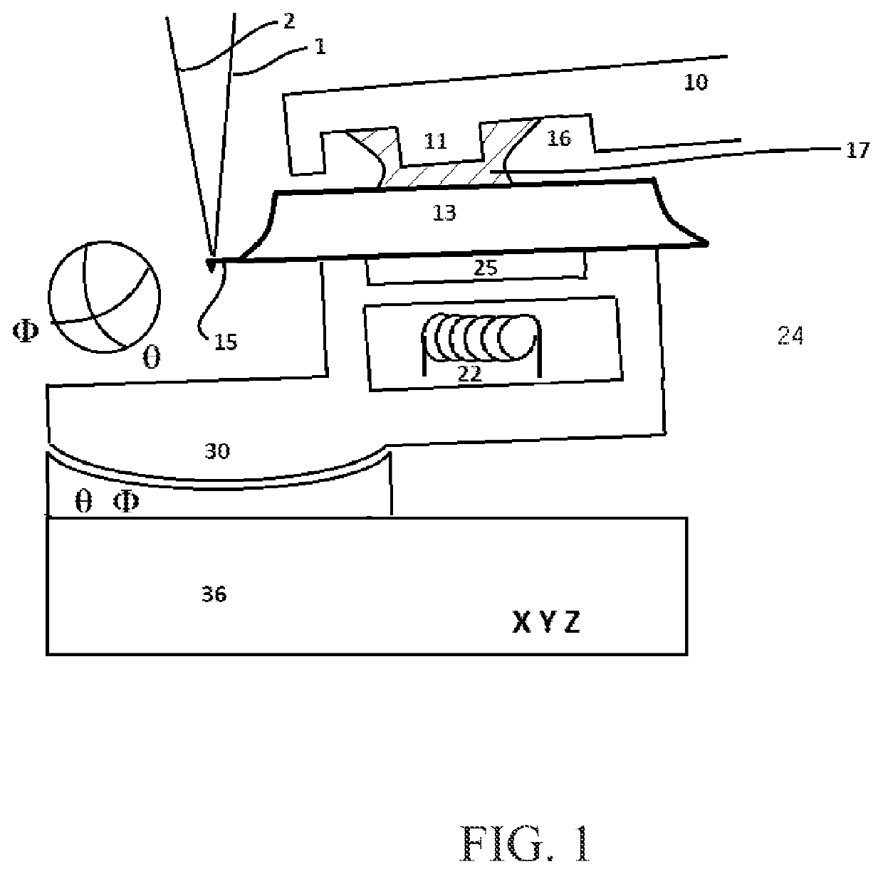
[0019]In a first implementation shown in FIG. 1, a releasable bonding element, a thermoplastic 17 for an exemplary implementation, is disposed between tip mounting arm 10 and probe mount substrate 13 which is temporarily held with a five axis positioning system 24 employing a vacuum chuck 25 disposed on a two axis gimbal stage 30 whose rotational center is ideally at the height of an AFM cantilever 15 extending from the probe mount substrate 13 thereby minimizing translation while tilting the probe is used to place the probe mount substrate into contacting proximity with the releasable bonding element. A heating element 22, integrally placed adjacent the vacuum chuck 25, is employed to melt the thermoplastic. The heating element may also be disposed upon the tip mounting arm however this arrangement is generally less favorable due to the requirement to provide electrical connection of the heating element as well as its bulk and mass would be added to the AFM head payload. The gimbal...


PUM


Abstract

This specification discloses a method and implementations improving the field of holding or mounting Scanning Probe Microscopy probe tips for use and alignment. Specifically, the invention allows probes to be mounted replaceably to a very small SPM actuator and aligned in 5 axis permitting alignment of cantilever to beam and reflected beam to detector. The invention allows for great simplification of SPM design while allowing reduction in sizes and masses of tip mounting apparatus thereby improving performance.

Description

BACKGROUNDField[0001]Implementations of the disclosure relate generally to the field of scanned probe microscopy (SPM) and specifically to the art of aligning, mounting, design, and replacement of disposable probes of the optical lever sensor type.Related Art[0002]In the field of SPM, the majority of probes are made with a MEMS process comprising a microns long sharp probe tip, a 40 to 500 microns long cantilever with one end holding said tip and the other end fixed on a substrate of glass, circuit board (PCB), metal, or silicon that is of millimeter scale. Although with respect to use in a SPM, only the cantilever and tip are functional. The substrate is of millimeter scale historically to allow mounting of the probe into a clip, vacuum mandrel, to allow for tweezer manipulation by hand and for transport and storage. The substrate support element is also used to either precisely register the probe to the mount if the mount has been precisely designed with matching registration elem...

Claims


Application Information

Patent Timeline
Patent Type & Authority Patents(United States)
IPC IPC(8): G01Q60/38
CPCG01Q60/38G01Q70/02
Inventor ERICKSON, ANDREW NORMANHOFSTATTER, KYLE ALFRED
Owner ANGSTROM SCI
Why Eureka
Try Eureka