Organic light emitting display (OLED)

a light-emitting display and organic technology, applied in the field of organic light-emitting displays, can solve the problems of increasing manufacturing costs and increasing manufacturing costs, and achieve the effects of uniform voltage, uniform brightness, and reduced output lines

Active Publication Date: 2007-02-22
SAMSUNG DISPLAY CO LTD
View PDF28 Cites 131 Cited by
  • Summary
  • Abstract
  • Description
  • Claims
  • Application Information

AI Technical Summary

Benefits of technology

[0013] The present invention, therefore, provides an Organic Light Emitting Display (OLED) that is capable of decreasing the number of output lines for a data driver using a demultiplexer, displaying an image with uniform brightness, and adjusting white balance with uniform voltage.

Problems solved by technology

Accordingly, the data driver internally includes a plurality of data Integrated Circuits (IC) to have m output lines, thereby increasing manufacturing cost.
In particular, as the resolution and size of the display panel increases, the data driver needs more data ICs, thereby further increasing the manufacturing cost.

Method used


Image

  • Organic light emitting display (OLED)
  • Organic light emitting display (OLED)
  • Organic light emitting display (OLED)

Examples


Embodiment Construction

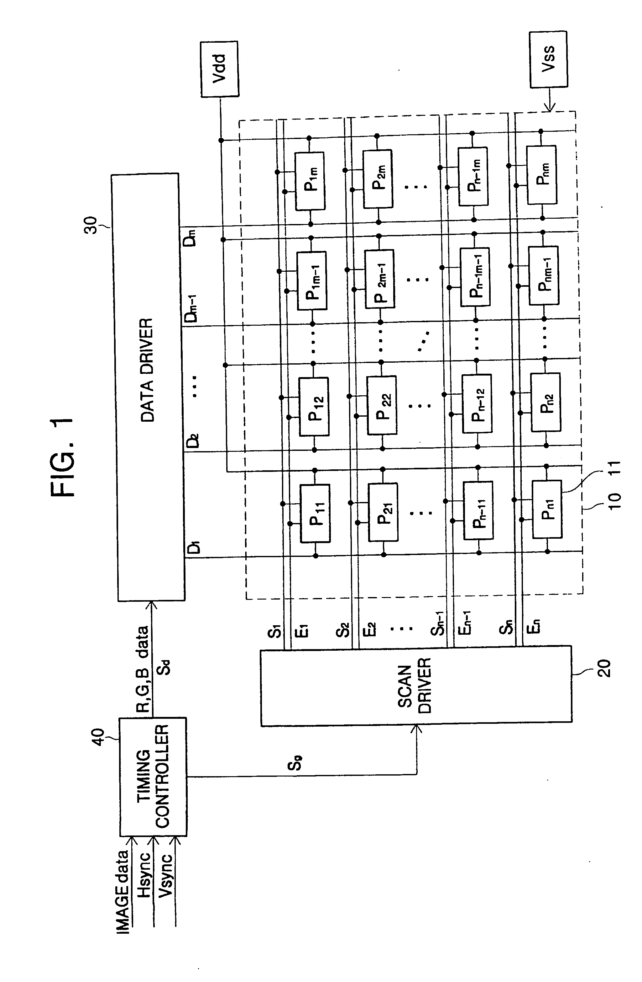
[0034]FIG. 1 is a block diagram of an OLED. Referring to FIG. 1, the OLED includes a display panel 10, a scan driver 20, a data driver 30, and a timing controller 40.

[0035] The display panel 10 includes a plurality of pixels P11 through Pnm formed in regions where a plurality of scan lines S1 through Sn, a plurality of emission control lines E1 through En, and a plurality of data lines D1 through Dm intersect each other. The respective pixels P11 through Pnm receive a first power supply Vdd and a second power supply Vss from the outside, and emit light corresponding to data signals transmitted from the plurality of data lines D1 through Dm, thereby displaying a predetermined image. Furthermore, in the pixels P11 through Pnm, their emission times are controlled by emission control signals transmitted through the emission control lines E1 through En.

[0036] The scan driver 20 generates scan signals in response to a scan control signal Sg from the timing controller 40, and sequentiall...


PUM


Abstract

An Organic Light Emitting Display (OLED) that is capable of decreasing the number of output lines for a data driver using a demultiplexer, displaying an image with uniform brightness, and adjusting white balance includes: a plurality of red, green and blue sub-pixels, and each sub-pixel is provided with an auxiliary capacitor to compensate a decreased driving voltage. The respective auxiliary capacitors are different in capacitance according to emission efficiency of the red, green and blue sub-pixels. The auxiliary capacitor of the green sub-pixel has a larger capacitance than the auxiliary capacitor of the red sub-pixel, and the auxiliary capacitor of the red sub-pixel has a larger capacitance than the auxiliary capacitor of the blue sub-pixel. This enables the white balance to be adjusted with the same data voltage.

Description

CLAIM OF PRIORITY [0001] This application makes reference to, incorporates the same herein, and claims all benefits accruing under 35 U.S.C. §119 from an application for ORGANIC ELECTROLUMINESCENT DISPLAY DEVICE earlier filed in the Korean Intellectual Property Office on the 16 of Aug. 2005 and there duly assigned Serial No. 10-2005-0074865. BACKGROUND OF THE INVENTION [0002] 1. Field of the Invention [0003] The present invention relates to an Organic Light Emitting Display (OLED), and more particularly, to an OLED that is capable of decreasing the number of output lines for a data driver using a demultiplexer, displaying an image with uniform brightness, and adjusting white balance. [0004] 2. Description of the Related Art [0005] Recently, various flat panel displays have been developed as alternatives to a relatively heavy and bulky cathode ray tube. Flat Panel Displays (FPDs) include Liquid Crystal Displays (LCDs), Field Emission Displays (FEDs), Plasma Display Panels (PDPs), Org...

Claims


Application Information

Patent Timeline
Patent Type & Authority Applications(United States)
IPC IPC(8): G09G3/30H05B44/00
CPCG09G3/3233G09G3/3291G09G2300/0819G09G2300/0852G09G2310/0297G09G2320/0238G09G2320/043G09G2320/0666H01L27/326H10K59/121H05B33/26
Inventor KIM, YANG-WAN
Owner SAMSUNG DISPLAY CO LTD
Why Eureka
Try Eureka