Fluid energy converter

a technology of energy converter and flue gas, which is applied in the direction of wind energy generation, wind motor with parallel air flow, liquid fuel engine components, etc., can solve the problems of inefficient gas gas conversion, high cost of machines, and high cost of energy conversion

Inactive Publication Date: 2007-02-22
VIRYD TECH
View PDF41 Cites 183 Cited by
  • Summary
  • Abstract
  • Description
  • Claims
  • Application Information

AI Technical Summary

Problems solved by technology

Energy conversion, from kinetic to mechanical, for gases can be inefficient, especially with windmills and wind turbines.
While some fluid energy converters for use with liquid fluids can achieve high efficiencies, these machines are expensive.
For example, although Francis water turbines can achieve efficiencies of over 90%, they are extremely expensive.

Method used


Image

  • Fluid energy converter
  • Fluid energy converter
  • Fluid energy converter

Examples


Embodiment Construction

” one will understand how the features of the system and methods provide several advantages over traditional systems and methods.

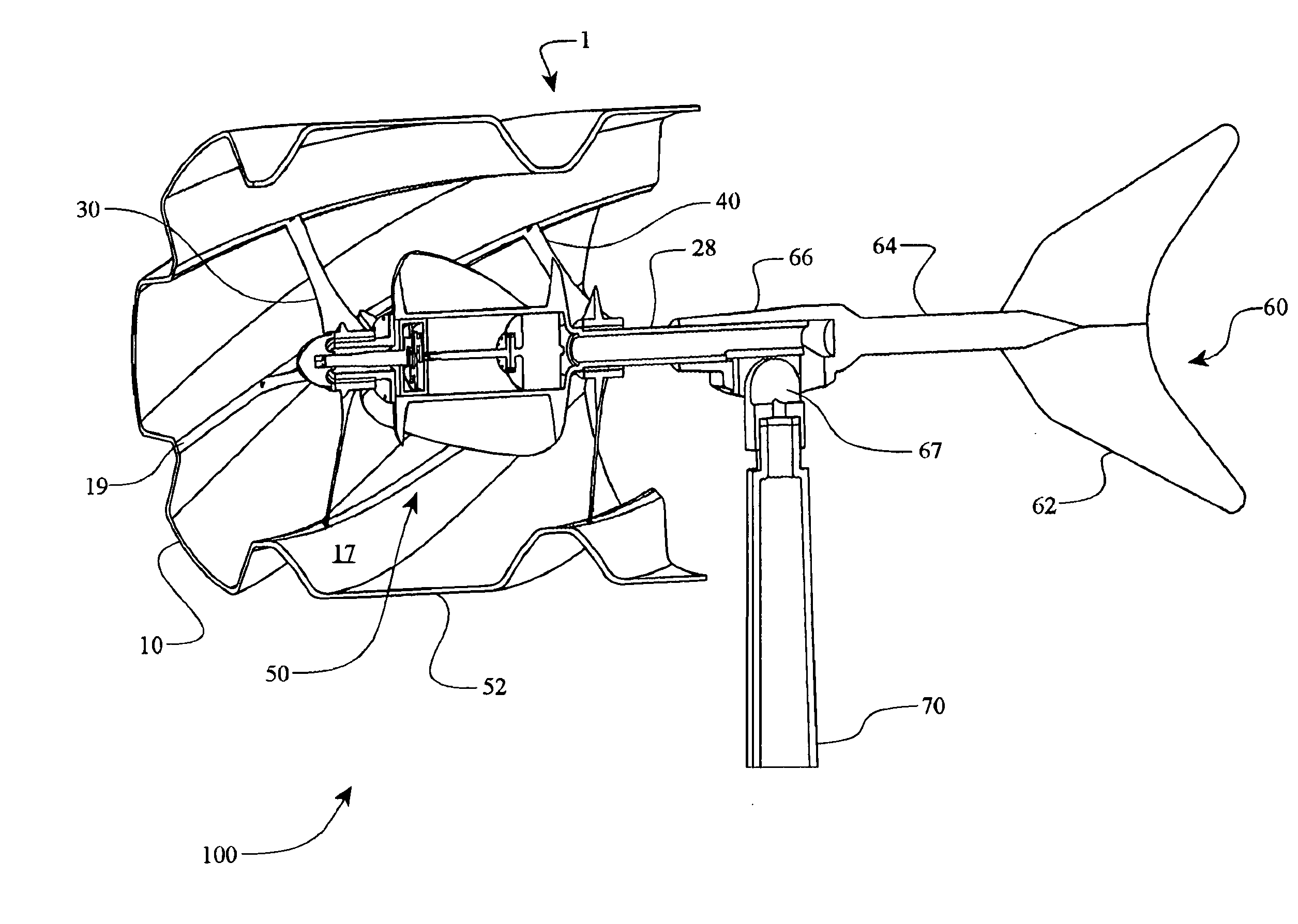
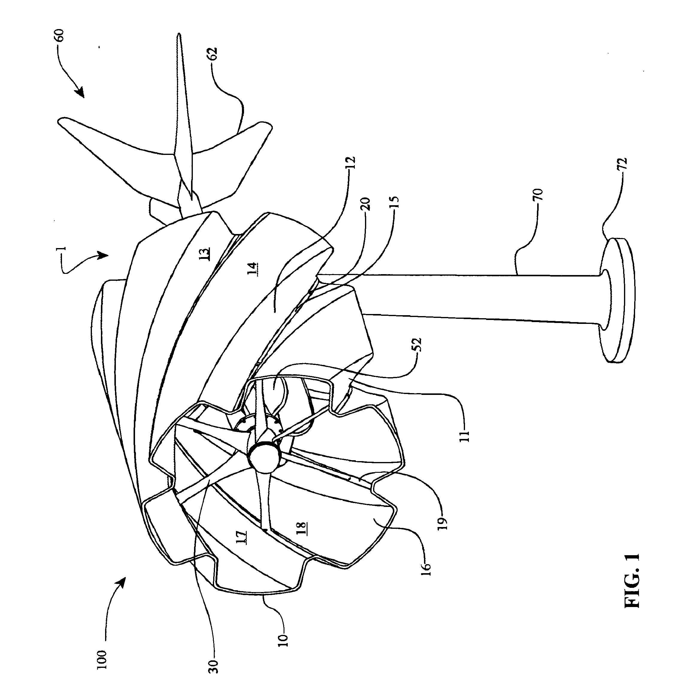
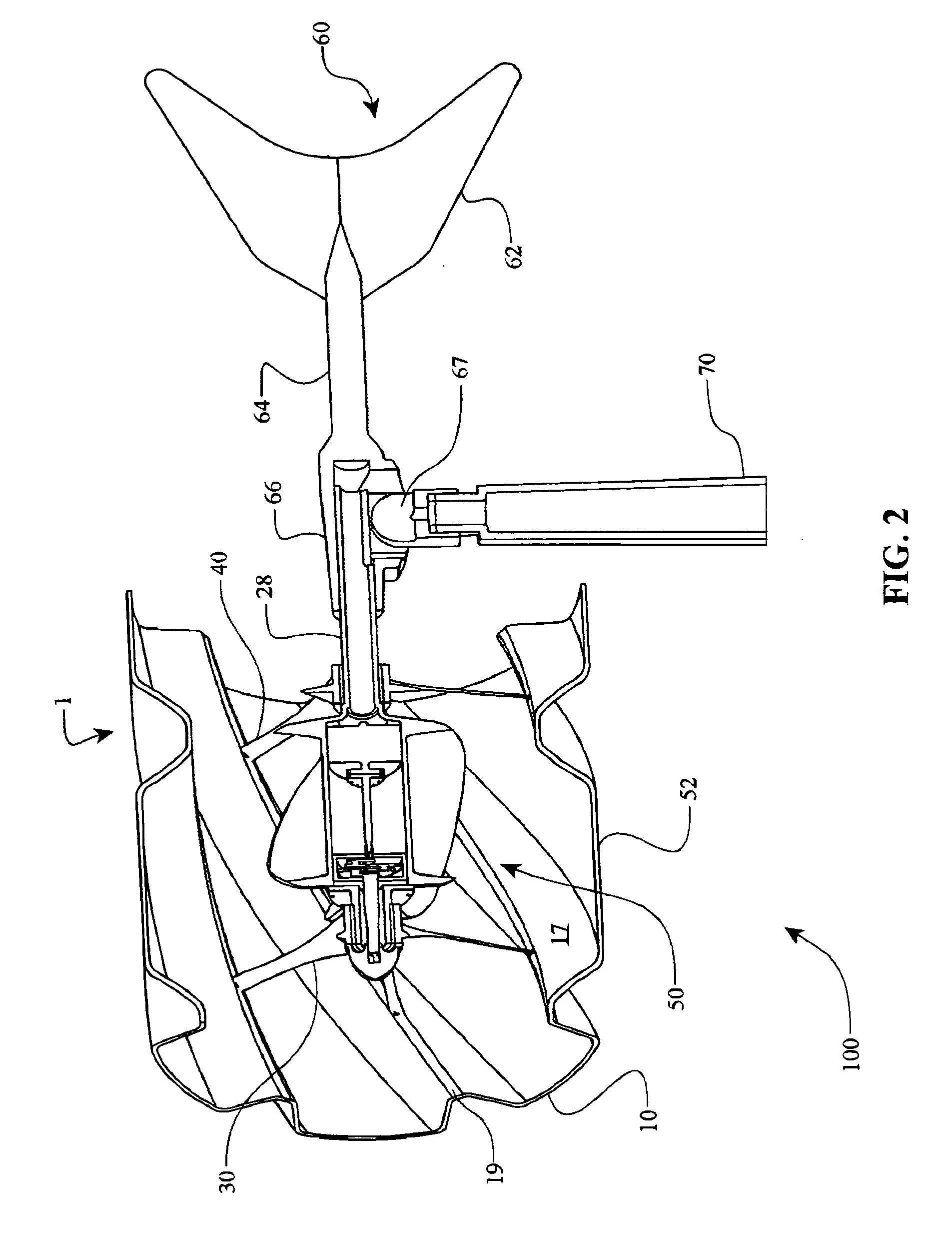
[0009] In one aspect, the invention relates to a tube for a fluid energy converter. The tube can have a generally cylindrical and hollow body that has an interior surface, an exterior surface, and a longitudinal axis. The tube can be provided with a plurality of helical grooves for capturing kinetic energy of a fluid stream as the fluid stream rotates the tube about the longitudinal axis.

[0010] In another aspect, the invention concerns a fluid energy converter having a longitudinal axis and a rotatable tube coaxial about the longitudinal axis. The rotatable tube can have helical grooves formed into both its exterior surface and interior surface for converting rotating mechanical energy into kinetic energy in a fluid.

[0011] In yet another aspect, the invention relates to a tube for a fluid energy converter. The tube can include a generally cylindrical and...


PUM


Abstract

Embodiments include apparatus and methods of fluid energy conversion. One embodiment relates to a tube for a fluid energy converter. The tube may include a generally cylindrical and hollow body having an interior surface, an exterior surface, and a longitudinal axis. Another embodiment includes a fluid energy converter having a longitudinal axis and a rotatable tube coaxial about the longitudinal axis. In some embodiments, the rotatable tube converts kinetic energy in a fluid into rotating mechanical energy, or converts rotating mechanical energy into kinetic energy in a fluid.

Description

RELATED APPLICATIONS [0001] This application claims the benefit of U.S. Provisional Application No. 60 / 710,225, filed Aug. 22, 2005, U.S. Provisional Application No. 60 / 710,339, filed Aug. 22, 2005, and U.S. Provisional Application No. 60 / 760,251, filed Jan. 19, 2006. Each of the above-identified applications is hereby incorporated by reference in its entirety.BACKGROUND OF THE INVENTION [0002] 1. Field of the Invention [0003] The field of the invention relates generally to fluid energy converters, and more particularly the invention relates to windmills and wind turbines. [0004] 2. Description of the Related Art [0005] Fluid energy converters typically use blades, propellers, or impellers to convert kinetic energy of a moving fluid into mechanical energy, or to convert mechanical energy into kinetic energy of a moving fluid stream. For example, windmills and waterwheels convert kinetic energy from the wind or water into rotating mechanical energy, and wind turbines and water turbin...

Claims


Application Information

Patent Timeline
Patent Type & Authority Applications(United States)
IPC IPC(8): F03B15/06
CPCF03B17/061Y02E10/728F03D1/0608F05B2210/16F05B2240/14F05B2240/33F05B2250/231F05B2250/25F05B2250/281F05B2250/71Y02E10/28Y02E10/721Y02E10/726Y10S415/908Y02P70/523Y02P70/527F03D13/20F03D9/25F03D1/04Y02E10/20Y02E10/72Y02P70/50
Inventor MILLER, DONALD C.
Owner VIRYD TECH
Why Eureka
Try Eureka