Use of Air Internal Energy and Devices

a technology of internal energy and air, applied in the direction of liquid fuel engine components, non-positive displacement fluid engines, cosmonautic vehicles, etc., can solve the problems of low efficiency, large turbines, heavy and expensive, etc., to increase the mass flow rate and speed of sound, increase the energy production of turbines, and increase the effect of air flow energy

Inactive Publication Date: 2008-03-13
HIRSHBERG ISRAEL
View PDF57 Cites 125 Cited by
  • Summary
  • Abstract
  • Description
  • Claims
  • Application Information

AI Technical Summary

Benefits of technology

[0033] Still another aspect of the invention is the starting process, which rotates the turbine for less than a minute in order to suck air from the nozzle, thus preventing static pressure rise within the nozzle and establishing steady state flow through the nozzle.
[0041] Still another aspect of the invention is the incorporation of water drain system that prevents water from accumulating within the nozzle or the rotor chamber.
[0053] Still another aspect of the invention is that said turboprop engine incorporates fuel injectors in the convergent nozzle to increase air flow energy and temperature thus increasing mass flow rate and speed of sound in the turbine to increase turbine energy production.

Problems solved by technology

As a result of this low efficiency, these wind turbines must be big in order to generate substantial electrical power.
Therefore they are big, heavy and expensive and their moving blades are dangerous to birds and aircraft.
Therefore these wind turbines are not installed on buildings of cities, where electrical power is in great demand.
Another inherent flaw of these wind turbines is their limit to operate on strong winds.
This is because the propeller blades are heavy—about 11 tons thus the centrifugal forces at high rotation speed becomes huge and there is no economic justification to design these blades to winds more than 25 meter per second.

Method used


Image

  • Use of Air Internal Energy and Devices
  • Use of Air Internal Energy and Devices
  • Use of Air Internal Energy and Devices

Examples


Embodiment Construction

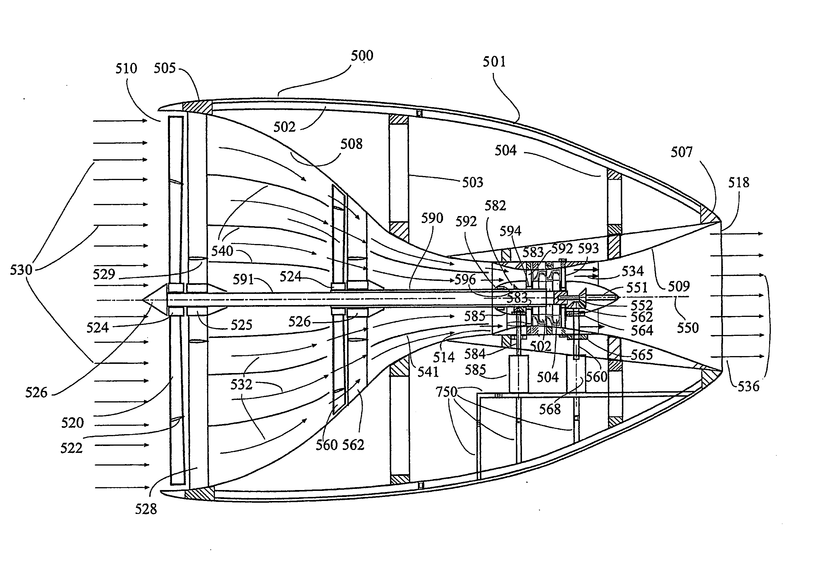
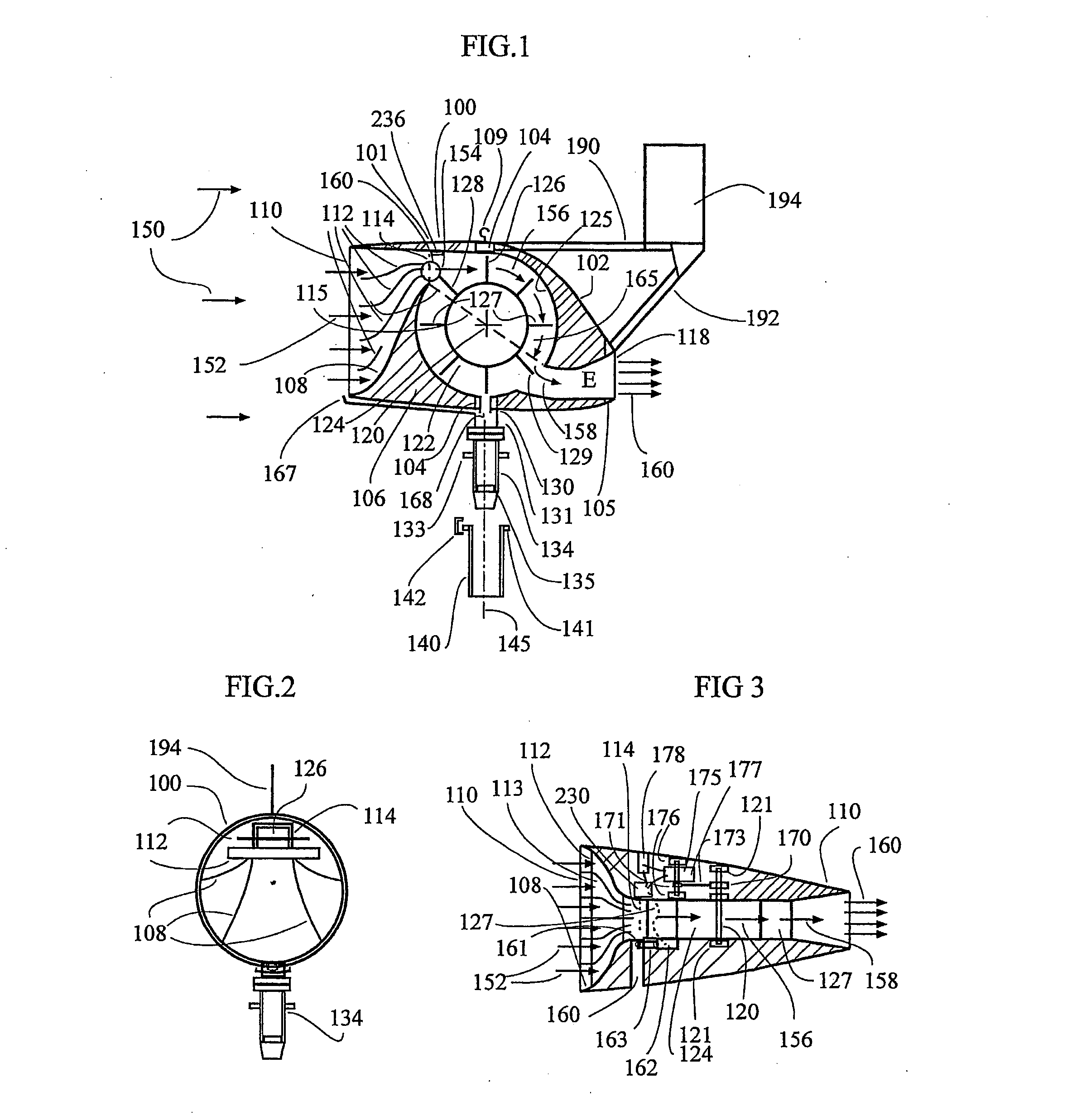
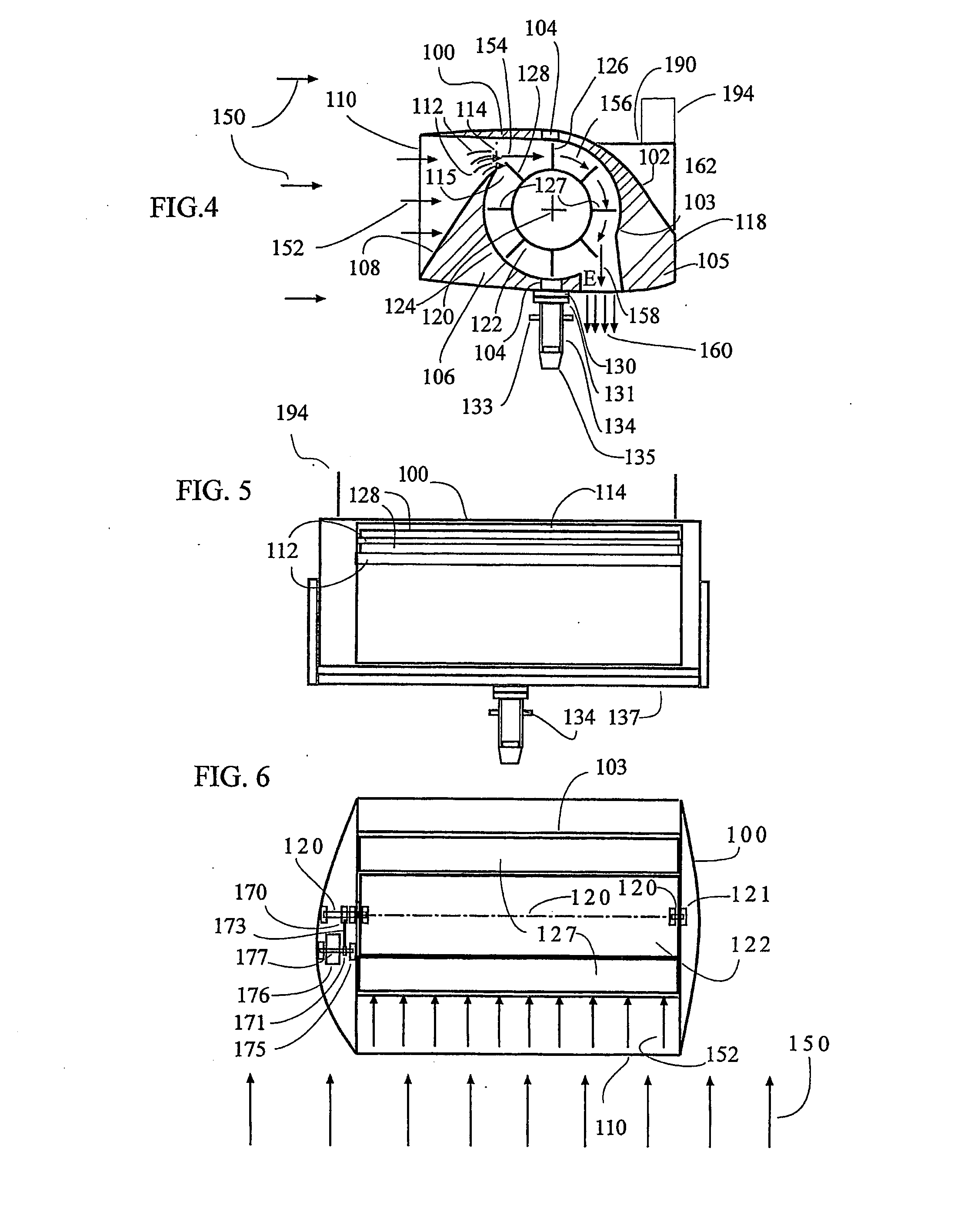
[0078] Today's wind turbines comprises of propellers, which are driven by airflow, i.e., wind. As wind increases, more kinetic energy is available to drive the propeller blades but since the propeller blades are big and heavy (about 11,000 kilograms per one blade), when the wind speed exceeds certain level, according to the blade strength and its attachment strength to the shaft, the rotation must be stopped to prevent centrifugal forces breaking the blade. Thus the air turbine stops its work and a lot of wind energy is wasted. On the other hand, when the wind is too weak, about 4 meter per second or less, even giant propellers are not put to work since the available kinetic energy is too small to rotate the giant air turbines. The present invention overcomes these obstacles and explains how the present invention air turbine can be compact and generates more electricity in weak winds as well as in high-speed winds.

[0079] Further, installing a powered fan that generates the airflow ...


PUM


Abstract

A method of converting air internal energy into useful kinetic energy is based on air flowing through substantially convergent nozzle, which accelerates the air as the cross section of the nozzle decreases thus increasing the air kinetic energy. The increment of the kinetic energy equals to the decrement of air internal energy, i.e., air temperature. Within said nozzle a turbine is placed to convert airflow kinetic energy into mechanical energy that transformed into electrical energy or transferred into a gearbox to provide driving moment. Devices uses this method could use natural wind as airflow source or artificial airflow means. Devices, which incorporate means to create airflow artificially, can be used as engines for land, sea and flying vehicle. Since air temperature drops within the nozzle, moisture condensation exists and liquid water can be accumulated for further use.

Description

FIELD OF THE INVENTION [0001] The present invention relates to methods and devices for increasing gas kinetic energy and generating electricity or mechanical energy from said energy. BACKGROUND OF THE INVENTION [0002] Today, wind turbines are quite popular in windy areas. Their design is similar to aircraft propellers. They are mounted on high towers to face the natural wind, which cause them to rotate and this rotation drives generators that generate electricity. A minimum wind speed of about 4 meters per second is required to start rotating the propeller. The electricity generated by the generator is then used by the turbine owners or transferred to an electrical grid. [0003] A good example for such a product is made by the a leading manufacturer in this field. The following data describes a 2 Megawatt generating machine. [0004] Diameter: 80 meter [0005] Swept area: 5,027 SQ meter [0006] Number of blades: 3 Tower Data [0007] Hub height (approx.) 60-67-78-100 meter Operational Da...

Claims


Application Information

Patent Timeline
Patent Type & Authority Applications(United States)
IPC IPC(8): F03D9/00
CPCF03D3/0454F03D3/0463F05B2240/133Y02B10/30F05B2240/2212Y02E10/74F05B2240/215Y02E10/728Y02P70/50Y02E70/30B05D1/36F03D3/02F03D9/11F03D9/32F03D9/25F03D80/40
Inventor HIRSHBERG, ISRAEL
Owner HIRSHBERG ISRAEL
Why Eureka
Try Eureka