Prosthetic valve

a valve and prosthesis technology, applied in the field of medical devices, can solve the problems of valve leaflets not functioning properly, patient discomfort and pain, and fluid flow substantially unidirectional along the length of the vessel,

Inactive Publication Date: 2007-02-22
COOK INC
View PDF4 Cites 264 Cited by
  • Summary
  • Abstract
  • Description
  • Claims
  • Application Information

AI Technical Summary

Benefits of technology

[0011] In one aspect of the present invention, a prosthetic valve for implantation in a body site is provided. The prosthetic valve includes at least one flexible member movable between a first position that permits fluid flow in a first direction and a second position that substantially prevents fluid flow in a second direction. The flexible member has a proximal portion and a distal portion. The valve includes a receptacle operatively connected to the proximal portion of flexible member. The receptacle has an expanded position adapted to receive fluid flowing in the second direction and a contracted position adapted to allow fluid flow through the valve in the first direction. The valve further includes an attachment portion operably connected to the receptacle for attaching the valve to the body site.
[0012] In another aspect of the present invention, a prosthetic valve for implantation into a body site is provided. The valve includes a flexible member and a receptacle together movable between an open configuration permitting fluid flow in a first direction and a closed confi...

Problems solved by technology

Frequently, fluid flows in a substantially unidirectional manner along the length of the vessel.
In the condition of venous insufficiency, the valve leaflets do not function properly.
Incompetent venous valves can result in symptoms such as swelling and varicose veins, causing great discomfort and pain to the patient.
If left untreated, venous insufficiency can result in excessive retrograde blood flow through incompetent venous valves, which can cause venous stasis ulcers of the skin.
Primary venous insufficiency typically occurs where the valve structure remains intact, but the vein is simply too large in relation to the leaflets so tha...

Method used


Image

  • Prosthetic valve
  • Prosthetic valve
  • Prosthetic valve

Examples


example 1

Formation of a Valve Device by Folding

[0106] In some embodiments of the present invention, the valve device 10 may be formed by folding, thereby reducing the number of seams that must be physically sealed. Many methods and designs for forming the valve device 10 may be used. By way of non-limiting example, the valve device 10 may preferably be formed by folding a sheet 200 of material to form the leaflets 16 and the receptacles 18 and the opening 26 therethrough. The sheet 200 for forming the valve device 10 may be made from any biocompatible material known to one skilled in the art, including the materials described above, such as, but not limited to SIS and THORALON®. The sheet 200 may be formed from multiple layers, including combinations of different materials or multiple layers of the same material where the sheets may be adhered together using the adhesives described above or mechanically adhered together, for example by sonic bonding. The sheet 200 may also be formed from wo...

example 2

Forming a Valve Device using a Mandrel

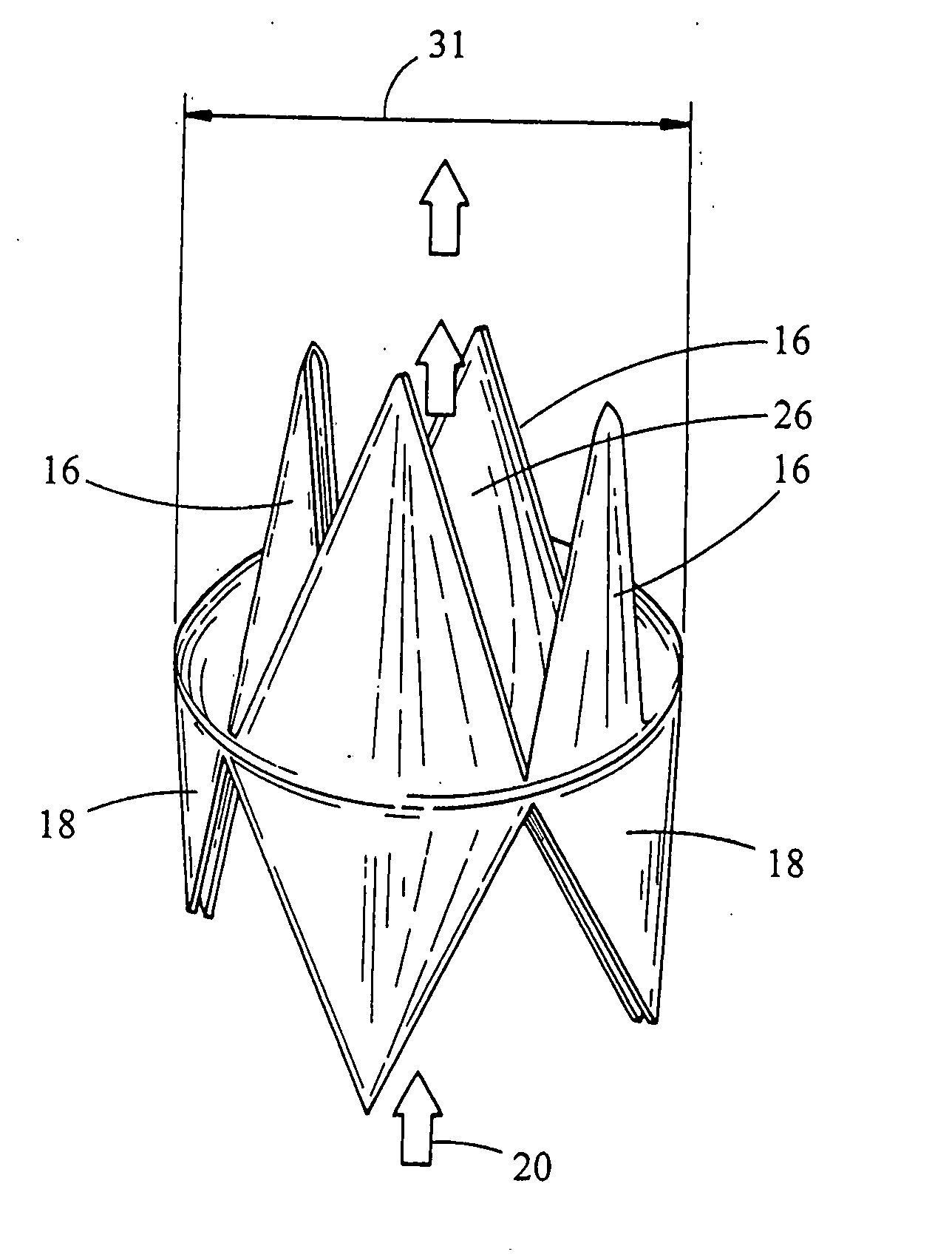
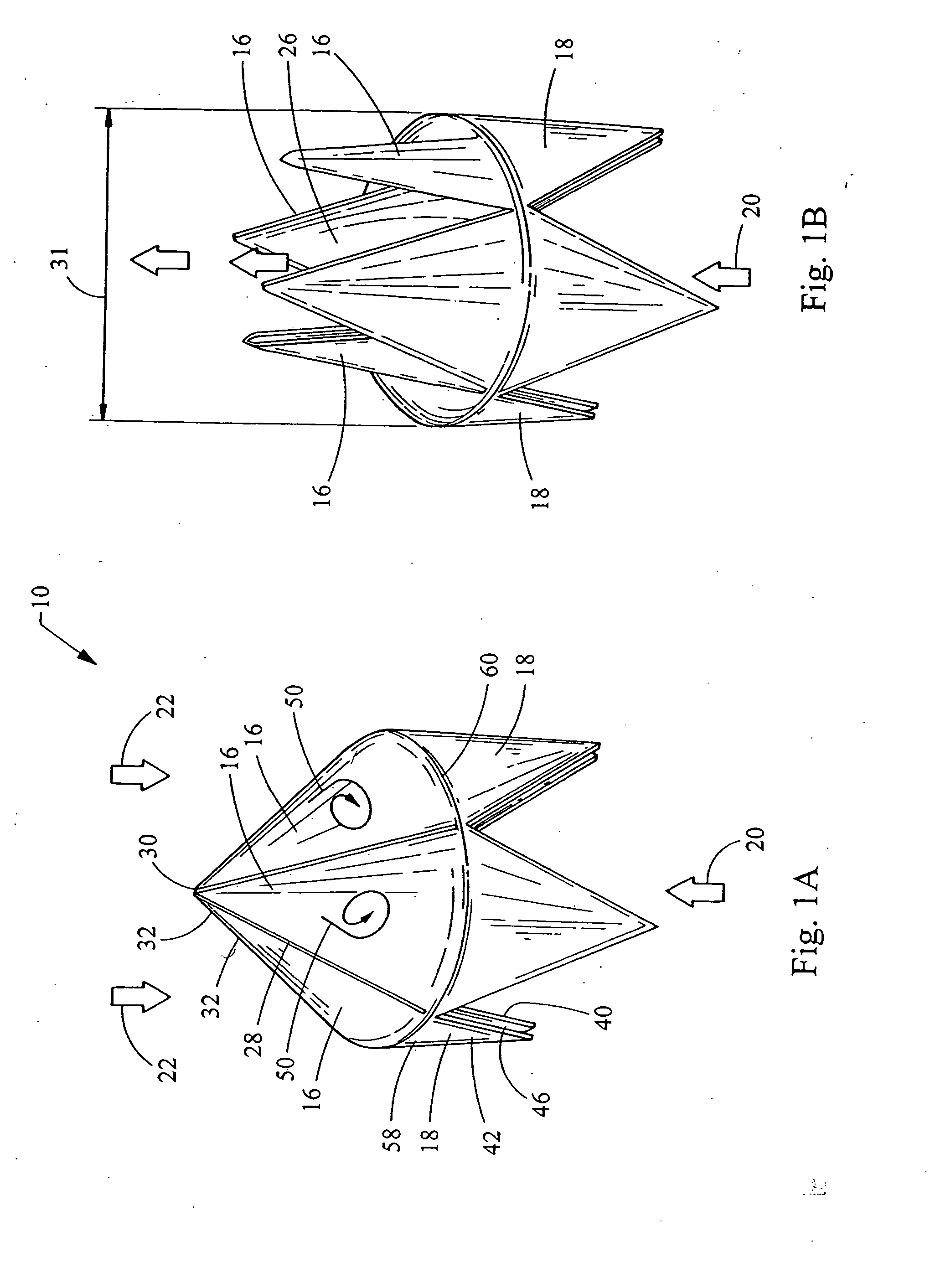
[0110] The valve device 10 may be formed from THORALON® using a mandrel to shape molten material in the form of a valve device. For example, the valve device 10 shown in FIGS. 1A and 1B having four leaflets 16 and receptacles 18 may be formed by using a triangular shaped, four-pronged, mandrel to form the receptacles 18 and leaflets 16 extending therefrom, with plates in between the four prongs to separate each of the receptacles 18 and to form the opening 26 in the valve device 10. The edge portion 58 may be formed on the mandrel being connected between each of the receptacles 18. Preparation of THORALON® for use with a mandrel, porous or nonporous, is described above.


PUM


Abstract

Prosthetic valves and a method for making a prosthetic valve for implantation in a body site are provided. The prosthetic valve includes at least one flexible member movable between a first position that permits fluid flow in a first direction and a second position that substantially prevents fluid flow in a second direction. The flexible member has a proximal portion and a distal portion. The valve includes a receptacle operatively connected to the proximal portion of flexible member. The receptacle has an expanded position adapted to receive fluid flowing in the second direction and a contracted position adapted to allow fluid flow through the valve in the first direction. The valve further includes an attachment portion operably connected to the receptacle for attaching the valve to the body site.

Description

RELATED APPLICATIONS [0001] This application claims the benefit of U.S. Provisional Application No. 60 / 709,956, filed Aug. 19, 2005, which is incorporated herein in its entirety.FIELD OF THE INVENTION [0002] The present invention relates to medical devices, and in particular to prosthetic valve devices, methods of making such devices, and methods of deploying such devices within a body site. BACKGROUND [0003] Many vessels in animals transport fluids from one bodily location to another. Frequently, fluid flows in a substantially unidirectional manner along the length of the vessel. For example, veins in the body transport blood to the heart and arteries carry blood away from the heart. [0004] In mammalian veins, natural valves are positioned along the length of the vessel in the form of leaflets disposed annularly along the inside wall of the vein which open to permit blood flow toward the heart and close to restrict back flow. These natural venous valves open to permit the flow of f...

Claims


Application Information

Patent Timeline
IPC IPC(8): A61F2/06
CPCA61F2/2418A61F2/2475A61F2220/0008A61F2230/0067A61F2220/0041A61F2220/0066A61F2230/0054A61F2220/0016
Inventor MELSHEIMER, JEFFRY S.
Owner COOK INC
Why Eureka
Try Eureka