Structure for fixing spindle motor to traverse chassis

a technology of structure and spindle motor, which is applied in the direction of magnetic recording, data recording, instruments, etc., can solve the problems of increasing the procurement cost of spindle motors, the fixing position may not be adjusted sufficiently,

Inactive Publication Date: 2007-02-22
FUNAI ELECTRIC CO LTD
View PDF3 Cites 8 Cited by
  • Summary
  • Abstract
  • Description
  • Claims
  • Application Information

AI Technical Summary

Benefits of technology

[0029] Hence, the present invention has been made in consideration of the above-described problems, and an object thereof is to provide an inexpensive fixing structure

Problems solved by technology

However, in the above-described structure for fixing the spindle motor 2 to the traverse chassis 1, since the fixing position of the spindle motor 2 has only a small adjustable margin in the second direction, the fixing posit

Method used


Image

  • Structure for fixing spindle motor to traverse chassis
  • Structure for fixing spindle motor to traverse chassis
  • Structure for fixing spindle motor to traverse chassis

Examples


Embodiment Construction

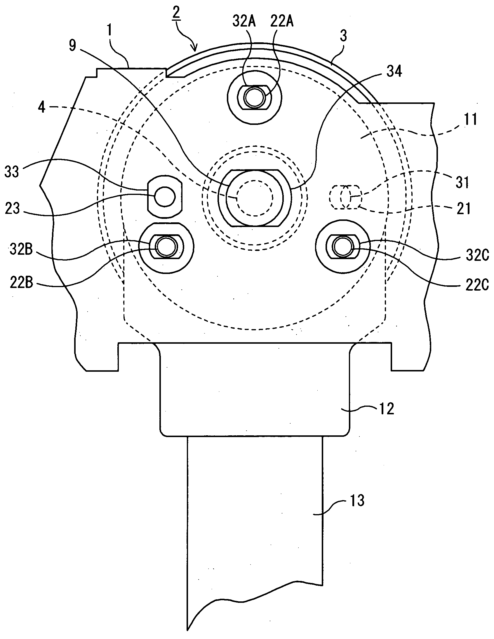
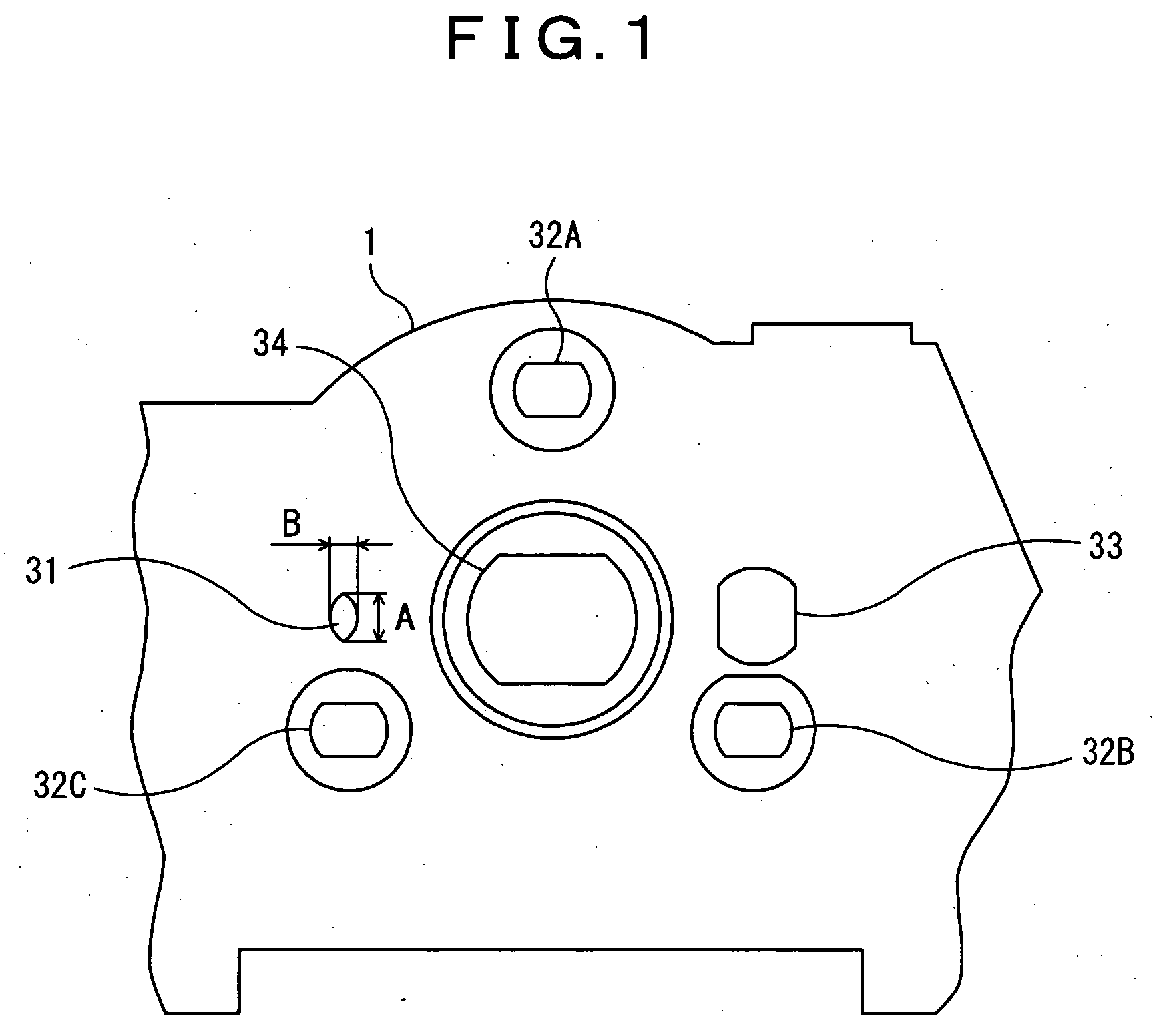
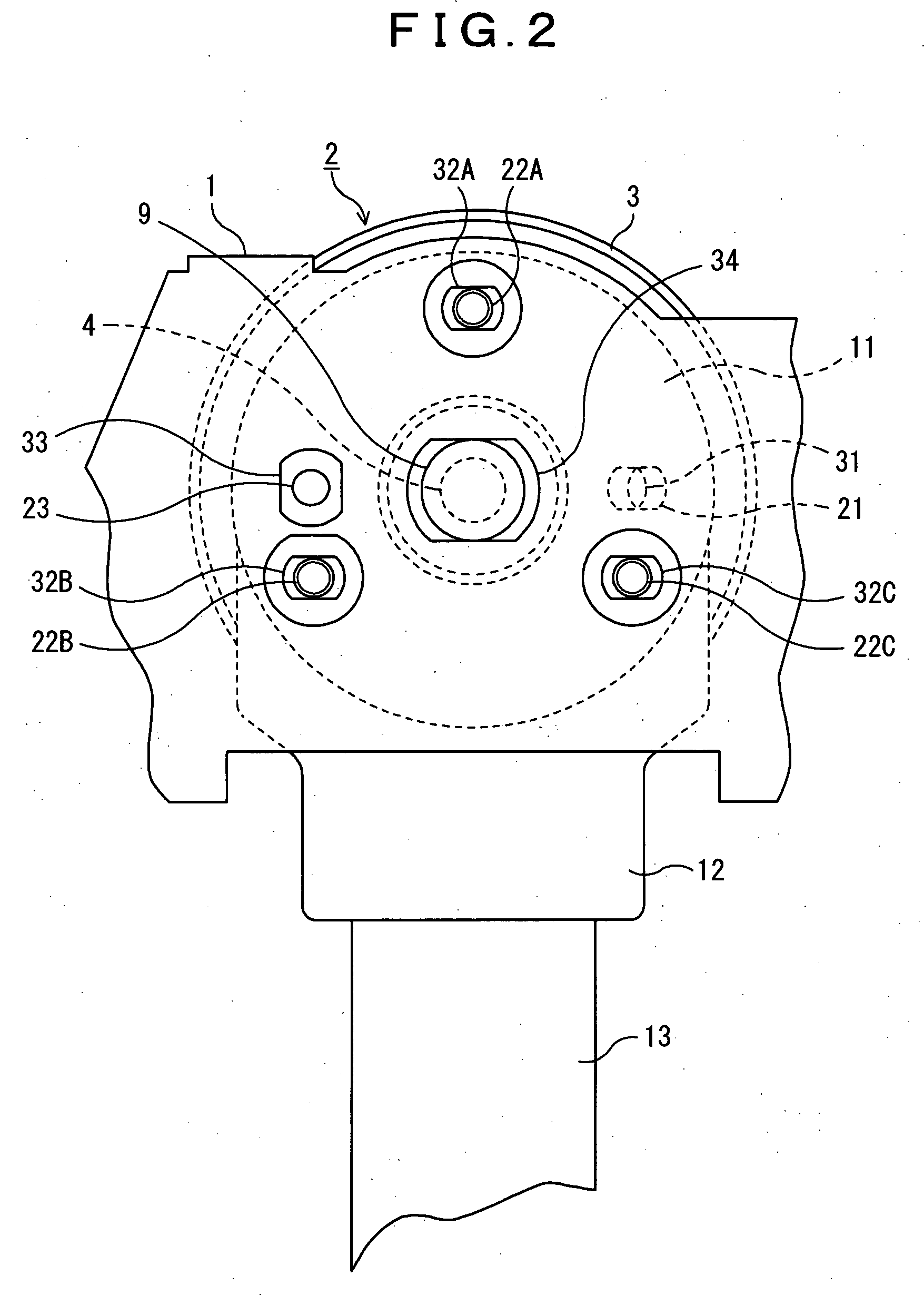
[0046] A structure for fixing a spindle motor to a traverse chassis in an optical disk apparatus according to an embodiment of the present invention will hereinafter be described in detail with reference to the accompanying drawings. FIG. 1 is a top view of a traverse chassis showing a structure for fixing a spindle motor to the traverse chassis in an optical disk apparatus according to an embodiment of the present invention, and FIG. 2 is a bottom view showing a state where the spindle motor is laid on the traverse chassis. It is noted that components shown in these figures and having the same names as well as performing the same functions as those shown in FIGS. 3 to 9 are designated by the same reference numerals to omit redundant description appropriately.

[0047] In the present embodiment, the spindle motor 2 is completely the same as that shown in FIGS. 3 to 5, and 7.

[0048] Meanwhile, as shown in FIGS. 1 and 2, as for the traverse chassis 1, the elongated center hole 34 for re...


PUM


Abstract

There is provided an inexpensive fixing structure in which the fixing position of a spindle motor against a traverse chassis is fixed in the direction of the movement of an optical pickup (first direction), while can be adjusted sufficiently in the direction perpendicular thereto (second direction). In the bottom surface of the spindle motor 2, there are formed: an elongated reference hole 21, the longitudinal direction of which extends in the radial direction centering on the main shaft 4; and three screw holes 22A, 22B, and 22C spaced out in the circumferential direction centering on the main shaft 4, and in the traverse chassis 1, there are formed: a protrusion 31 adapted to be engaged with the reference hole 21 when the reference hole 21 is arranged in an elongated manner in the second direction; and elongated through holes 32A, 32B, and 32C elongated in the second direction at the positions corresponding to those of the respective screw holes 22A, 22B, and 22C. The cross-sectional width A of the protrusion 31 in the first direction is approximately the same as the width of the reference hole 21, while the cross-sectional width B in the second direction is smaller than the cross-sectional width A in the first direction.

Description

BACKGROUND OF THE INVENTION [0001] 1. Field of the Invention [0002] The present invention relates to an optical disk apparatus for reproducing / recording information from / onto an optical disk such as CD or DVD, an information recording medium, and particularly to a structure for fixing a spindle motor for rotating such an optical disk onto a traverse chassis. [0003] 2. Description of the Prior Art [0004] Optical disk apparatuses are generally adapted to rotate a clamped optical disk and to apply a laser beam to the recording surface of the optical disk to write information onto the recording surface (recording), and further to receive a laser beam reflected at the recording surface of the optical disk to read information from the recording surface (reproduction). Reproduction and recording are performed through an optical pickup adapted to move back and forth in the radial direction along the recording surface of the optical disk. The movement of the optical pickup is generally guide...

Claims


Application Information

Patent Timeline
IPC IPC(8): G11B19/20
CPCG11B19/2009
Inventor MURAKAMI, TAKAYUKI
Owner FUNAI ELECTRIC CO LTD
Why Eureka
Try Eureka