Eureka AIR delivers breakthrough ideas for toughest innovation challenges, trusted by R&D personnel around the world.

Slit nozzle and apparatus for supplying treatment liquid using slit nozzle

Inactive Publication Date: 2007-03-01
TOKYO OHKA KOGYO CO LTD
View PDF1 Cites 3 Cited by
  • Summary
  • Abstract
  • Description
  • Claims
  • Application Information

AI Technical Summary

Benefits of technology

[0016] By using a hard material (metal) as one of the slit nozzle portions and a soft material (resin) as the other, when the two portions are joined, the soft material adheres to the hard material, and thereby no gaps which may cause capillary action are generated. In addition, since the present invention does not require such accuracy of the processing as the conventional art, it is possible to reduce the processing time.
[0017] A plurality of slit nozzles each of which comprises left and right portions made of different materials may be used so as to reduce the time required for supplying a treatment liquid and finish coating within a short period of time even in a case of forming a thick film.
[0018] The slit nozzle comprising left and right portions made of a different material may be provided in a circulating passage of a treatment liquid whose temperature is controlled. With this, it is possible to reduce the time required for supplying a treatment liquid, and also control the temperature of the treatment liquid to be a desired one within a short period of time.

Problems solved by technology

However, as an object to be treated becomes large, a single slit nozzle has limits with respect to the time and the amount of supplying a coating liquid.
For example, if it takes too much time from the start of supplying a coating liquid to the finish, non-uniformity undesirably occurs.
This problem occurs when a coating liquid is supplied so as to form a thick coating.
It takes a lot of time and labor to perform such accurate processing, and also it is expensive.
In addition, even if accuracy of the processing is improved as much as possible, a very small gap is generated partly in the boundary of the two portions of the slit nozzle due to the large width of the slit nozzle, in which capillary action occurs and the treatment liquid soaks therethrough.

Method used


Image

  • Slit nozzle and apparatus for supplying treatment liquid using slit nozzle
  • Slit nozzle and apparatus for supplying treatment liquid using slit nozzle
  • Slit nozzle and apparatus for supplying treatment liquid using slit nozzle

Examples


Embodiment Construction

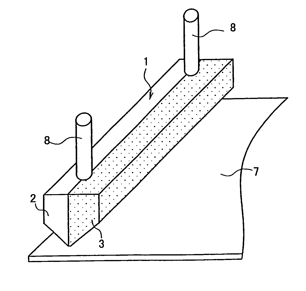
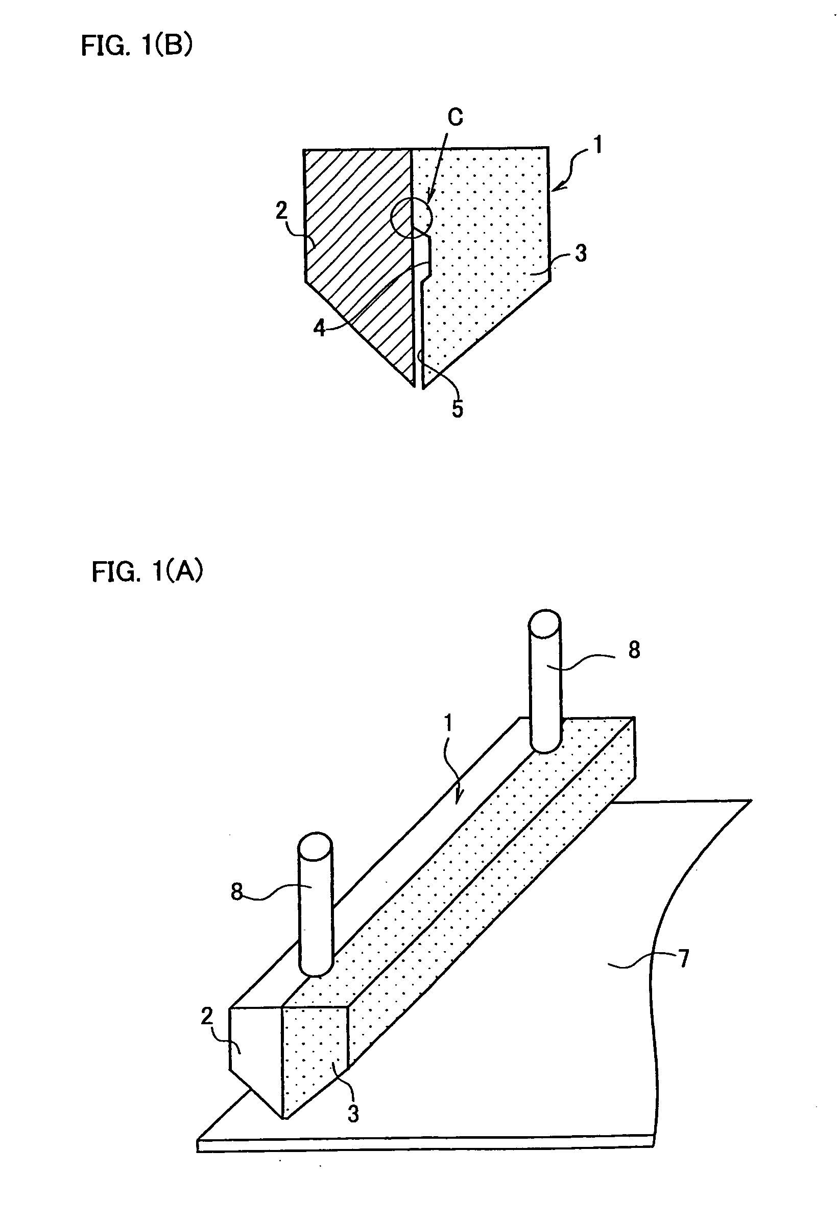
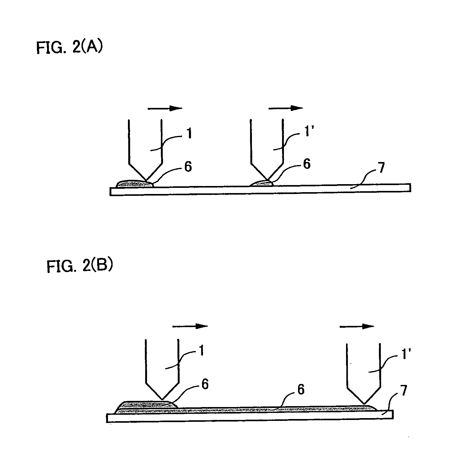
[0025] Hereinafter, embodiments according to the present invention will be explained with reference to the attached drawings. FIGS. 1A and 1B are a perspective view and an enlarged sectional view of a slit nozzle according to the present invention, FIGS. 2A and 2B are a schematic view showing the case where a treatment liquid is supplied by using a plurality of slit nozzles according to the present invention, FIG. 3 is a schematic view showing direct temperature control which comprises a slit nozzle according to the present invention and a temperature controller, and FIG. 4 is a schematic view showing indirect temperature control according to the conventional apparatus.

[0026] As shown in FIG. 1, a slit nozzle 1 is constructed of a left portion 2 made of titanium and a right portion 3 made of PPS (polyphenylene sulfide) which are joined with respect to each other. The right portion 3 has a recessed portion 4 for forming a manifold (lateral passage) and a flat surface 5 for forming a...


PUM


Abstract

A slit nozzle which is easily manufactured and in which no capillary action occurs, and an apparatus for supplying a treatment liquid using the slit nozzle are disclosed. The slit nozzle is constructed of a left portion and a right portion joined to each other, one of which is made of metal and the other of which is made of resin. In the apparatus for supplying a treatment liquid using one or more of the slit nozzles, the slit nozzles are provided in a circulating passage of a treatment liquid whose temperature is controlled.

Description

BACKGROUND OF THE INVENTION [0001] 1. Field of the Invention [0002] The present invention relates to a slit nozzle comprising left and right portions made of different materials, and an apparatus for supplying a treatment liquid using the slit nozzle. [0003] 2. Description of Background Art [0004] Conventionally, there has been known a slit nozzle in which an opening of a predetermined width for ejecting a coating liquid is provided, and the nozzle is moved relatively with respect to an object to be treated so as to apply a coating liquid to the object to be treated in a predetermined width. With the slit nozzle having an opening of a predetermined width, it is possible to apply a coating liquid efficiently without wasting the coating liquid. [0005] However, as an object to be treated becomes large, a single slit nozzle has limits with respect to the time and the amount of supplying a coating liquid. For example, if it takes too much time from the start of supplying a coating liquid...

Claims


Application Information

Patent Timeline
IPC IPC(8): B05C5/00B05C11/00B05B1/14
CPCB05C5/0254B05C5/0262B05C11/1042
Inventor SHIMAI, FUTOSHIKAWATA, SHIGERU
Owner TOKYO OHKA KOGYO CO LTD
Why Eureka
Eureka Blog
Learn More