Motorcycle rear fender structure

Inactive Publication Date: 2007-03-01
KAWASAKI HEAVY IND LTD
View PDF7 Cites 10 Cited by
  • Summary
  • Abstract
  • Description
  • Claims
  • Application Information

AI Technical Summary

Benefits of technology

[0010] According to a preferred embodiment of the present invention, the upper fender and the lower fender may cooperatively define a space therebetween so that, even when the present invention is applied to a motorcycle of a kind, in which an exhaust muffler is disposed proximate to and below the motorcycle seat, radiant heat emitted from the exhaust muffler can be insulated by the space, delimited between the upper and lower fenders, to thereby preventing such radiant heat from being transmitted to the interior space in the upper fender. Accordingly, a possible exposure of component parts such as electric component parts disposed within the interior space can advantageously be suppressed.
[0011] The upper fender is preferably formed as a molded product, which is formed integrally with an upwardly protruding hook and which has a mold hole left below a free end of the hook. Where the upper fender is formed integrally with such upwardly protruding hook, not only can the upper fender be manufactured by means of a plastic molding technique with the use of, for example, a simplified molding assembly including relatively movable upper and lower molds, the hook can easily formed through the mold hole left therein.
[0012] In another preferred embodiment of the present invention, one of the upper fender and the lower fender may be provided with an engagement hole, in which case the other of the upper fender and the lower fender is provided with an engagement piece engageable in the engagement hole. According to this structural feature, since the lower fender can be fixed to the upper fender by means of a simplified coupling means for engaging the engagement piece in the engagement hole, the number of assembling steps can advantageously be reduced as compared with the coupling with the use of a coupling means such as screws or bolts and nuts.
[0013] Preferably, the upper fender has a bottom wall and s

Problems solved by technology

Consequently, the rear wheel fender tends to take a relatively complicated rugged configuration and is generally manufactured as a resin molded article.
However, considering that the rear wheel fender is so shaped and so designed as to prevent water and/or mud, splashed from the motorcycle r

Method used


Image

  • Motorcycle rear fender structure
  • Motorcycle rear fender structure
  • Motorcycle rear fender structure

Examples


Embodiment Construction

[0032] A preferred embodiment of the present invention will be described in detail with reference to the accompanying drawings.

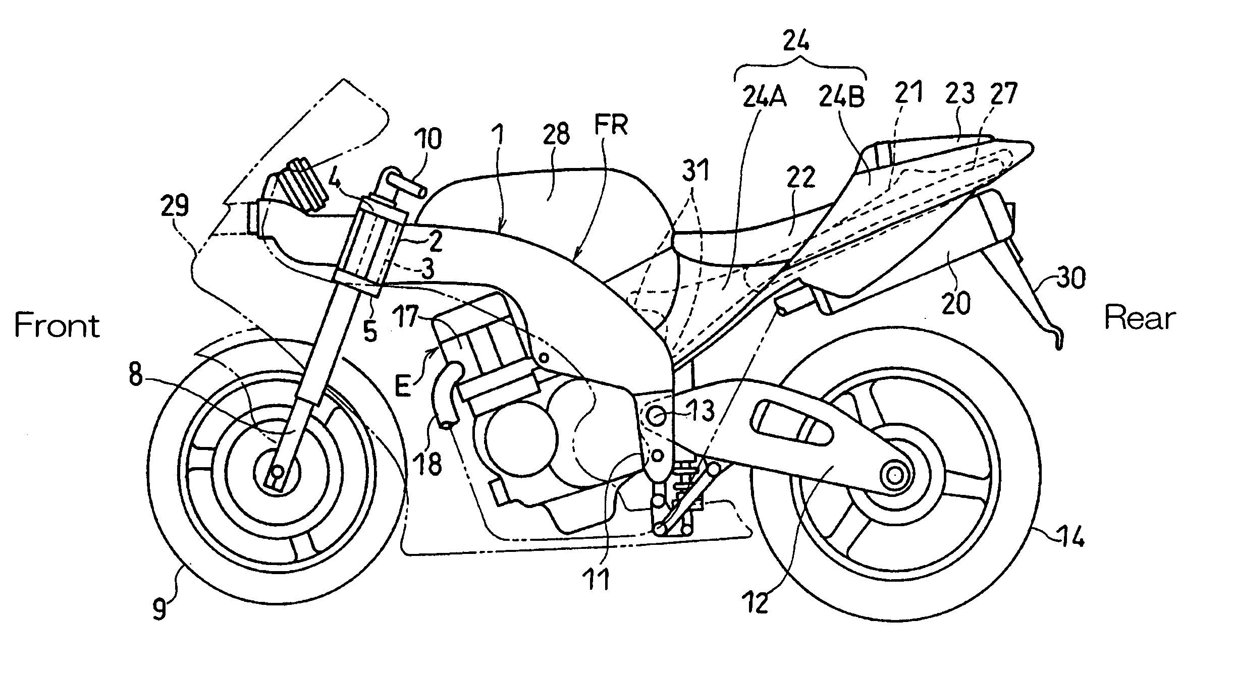
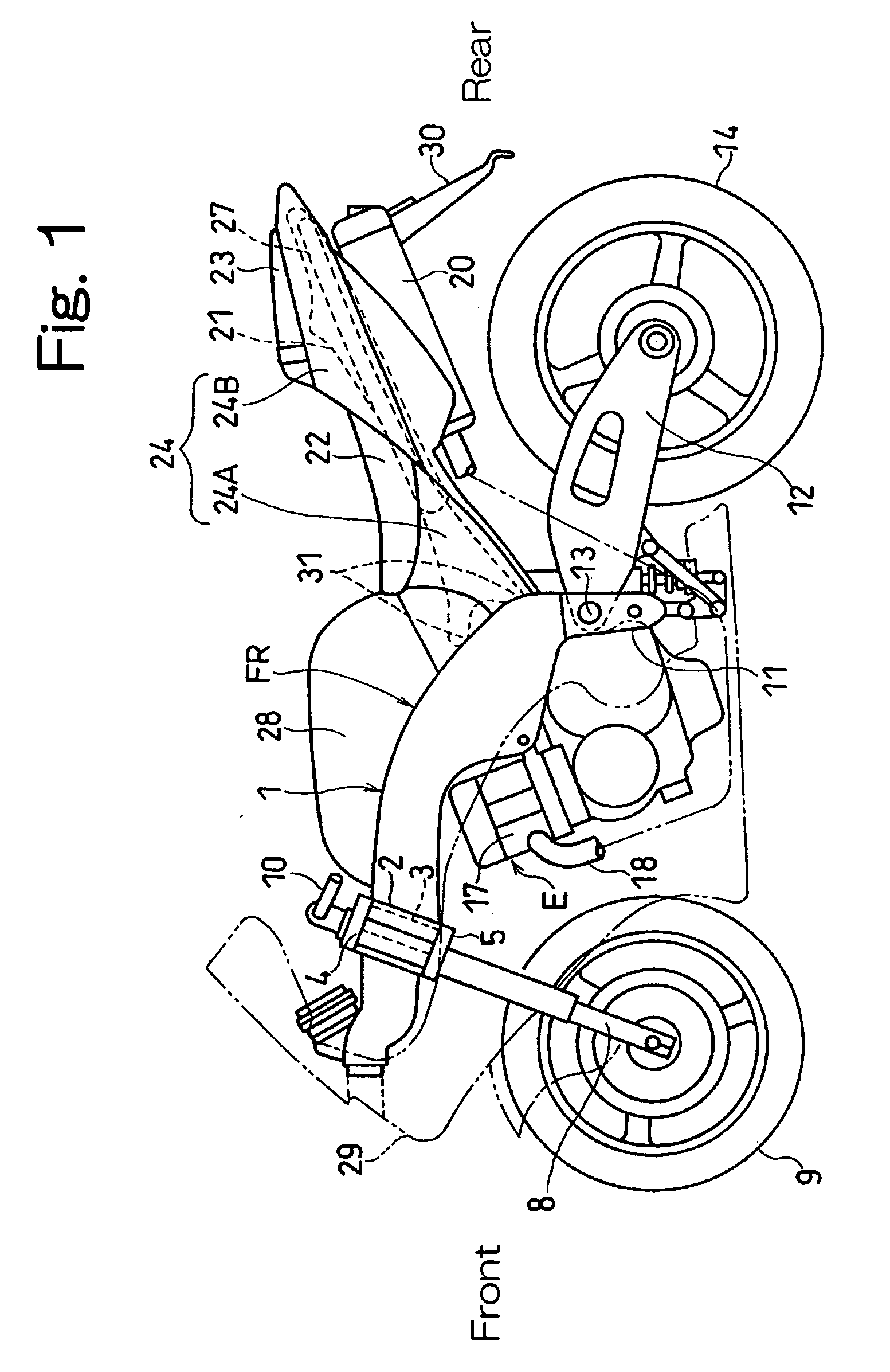
[0033]FIG. 1 schematically illustrates a side view of a motorcycle equipped with a rear wheel fender structure according to the embodiment of the present invention. The motorcycle shown therein includes a motorcycle frame structure FR made up of a main frame 1, forming a front part of the motorcycle frame structure FR.

[0034] The main frame 1 includes a head tube 2 rigidly connected to a front portion of the main frame 1 and a steering shaft 3 is rotatably supported by the head tube 2. Upper and lower brackets 4 and 5 are supported by the head tube 2 through the steering shaft 3. Front fork members 8 are supported by the upper and lower brackets 4 and 5, and a front wheel 9 is rotatably supported by and between respective lower ends of the front fork members 8. A handlebar 10 is mounted on the upper bracket 4, which lies at respective upper ends of the fron...


PUM


Abstract

To provide a rear wheel fender structure for motorcycles, which can be molded with a simplified and inexpensive mold assembly even where the rear wheel finder is so designed and so structured as to permit component parts to be fitted thereto and as to block the splashing of water and/or mud, the rear wheel fender structure 27 is positioned above the motorcycle rear wheel 14 and includes an upper fender 39 and a lower fender 40 secured to a bottom region of the upper fender 39. An adiabatic space 99 is preferably formed between the upper fender 39 and the lower fender 40.

Description

BACKGROUND OF THE INVENTION [0001] 1. Field of the Invention [0002] The present invention relates to a motorcycle rear fender structure secured to a motorcycle frame structure above a motorcycle rear wheel. [0003] 2. Description of the Prior Art [0004] In some of the motorcycles now in use, a rear frame substructure forming a rear portion of the motorcycle frame structure is generally provided with a rear wheel fender positioned above the rear drive wheel, a tail cover for covering an outer region of the rear frame substructure except for the position, where a driver's seat or a driver's seat and a fellow passenger's seat are installed, to provide an appealing appearance, and a storage space positioned below a fellow passenger's seat and including, for example, a glove box, a tool box and / or a casing for accommodating electric components. In general, the glove box and the tool box make use of the rear wheel fender as their bottom surfaces, of a top opening of the tail cover as an ac...

Claims


Application Information

Patent Timeline
IPC IPC(8): B62D61/00
CPCB62J1/12B62J15/00B62K19/46
Inventor OKABE, YASUHISABEPPU, HIDEOFUJIMOTO, YUKINORIFUJII, KATSUJI
Owner KAWASAKI HEAVY IND LTD
Why Eureka
Try Eureka