X-ray diagnostic apparatus

Active Publication Date: 2009-03-26
TOSHIBA MEDICAL SYST CORP
View PDF3 Cites 5 Cited by
  • Summary
  • Abstract
  • Description
  • Claims
  • Application Information

AI Technical Summary

Benefits of technology

[0019]Accordingly, an advantage of an aspect of the present invention is to provide the X-ray diagnostic apparatus that the center of the ex

Problems solved by technology

However, when the retention feature is moved, the center of the detection range of the X-ray detector might not be able to be matched to the test object of the subject, because the retention feature have a constant movement stroke's and evades interference with the tabletop etc. the retention feature, and the movement of the retention feature is limited.
The retention feature is not stopped easily at a prescribed position, and there is a problem that easily matching the center of the detection range of the X-ray detector to the test object after it changes becomes difficult because the inertia of the retention feature is large.
There is a problem of becom

Method used


Image

  • X-ray diagnostic apparatus
  • X-ray diagnostic apparatus
  • X-ray diagnostic apparatus

Examples


embodiment 1

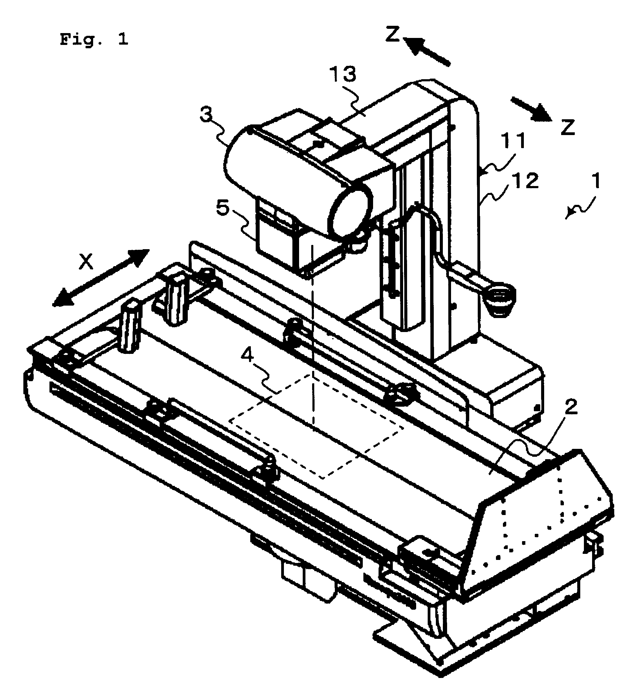
[0050]A first embodiment in accordance with the present invention will be explained with reference to FIGS. 1 to 11. FIG. 1 is an oblique perspective figure of an X-ray diagnostic apparatus according to a first embodiment.

[0051]As shown in FIG. 1, a X-ray diagnostic apparatus 1 is composed tabletop 2 that puts a subject, a X-ray tube 3 that irradiates X-rays, a X-ray detector 4 that detects X-rays that passed the subject, and a beam-limiting device 5 that forms the exposure field of X-rays to X-ray detector 4. X-ray tube 3 and X-ray detector 4 are put on both sides of tabletop2.

[0052]Tabletop 2 is composed movable in a shorter direction of tabletop 2 (X-way in FIG. 1). The shorter direction of tabletop 2 is an orthogonal direction in the direction of body axis of a subject. The longer direction of tabletop2 (Z-way in FIG. 1) is equal to the direction of the direction of body axis of a subject.

[0053]X-ray tube 3 is maintained in a retention feature 11. Retention feature 11 has a brac...

embodiment 2

[0124]A second embodiment in accordance with the present invention will be explained with reference to FIG. 12. FIG. 12 is a functional block diagram of the X-ray diagnostic apparatus according to a second embodiment. The second embodiment is different from the first embodiment in the following two points.

[0125]The first different point is the relative movement of imaging system structure by operating of center transfer operation unit 74.

[0126]In the second embodiment, the moving destination at the center of the exposure field is directed by operating center transfer operation unit 74. To locate the center of the exposure field in the moving destination at the directed center, imaging system structure is relative movement.

[0127]The second different point is operating information processing unit 8 has judgment unit 85. Judgment unit 85 judges whether part or all in the exposure field 4a exceed the detection range of X-ray detector 4 when the center of exposure field 4a move based on ...

embodiment 3

[0159]In the first and second embodiments, retention feature 11 maintains X-ray tube 3 and beam-limiting device 5. It is composed to move along the longer direction of tabletop 2, and it is composed to move X-ray detector 4 with X-ray tube 3 and beam-limiting device 5 as one body.

[0160]In the third embodiment, X-ray tube 3 and X-ray detector 4 is composed the vertical plane including the body axis of subject rotatably with one arbitrary point between X-ray tube 3 and X-ray detector 4 is centers.

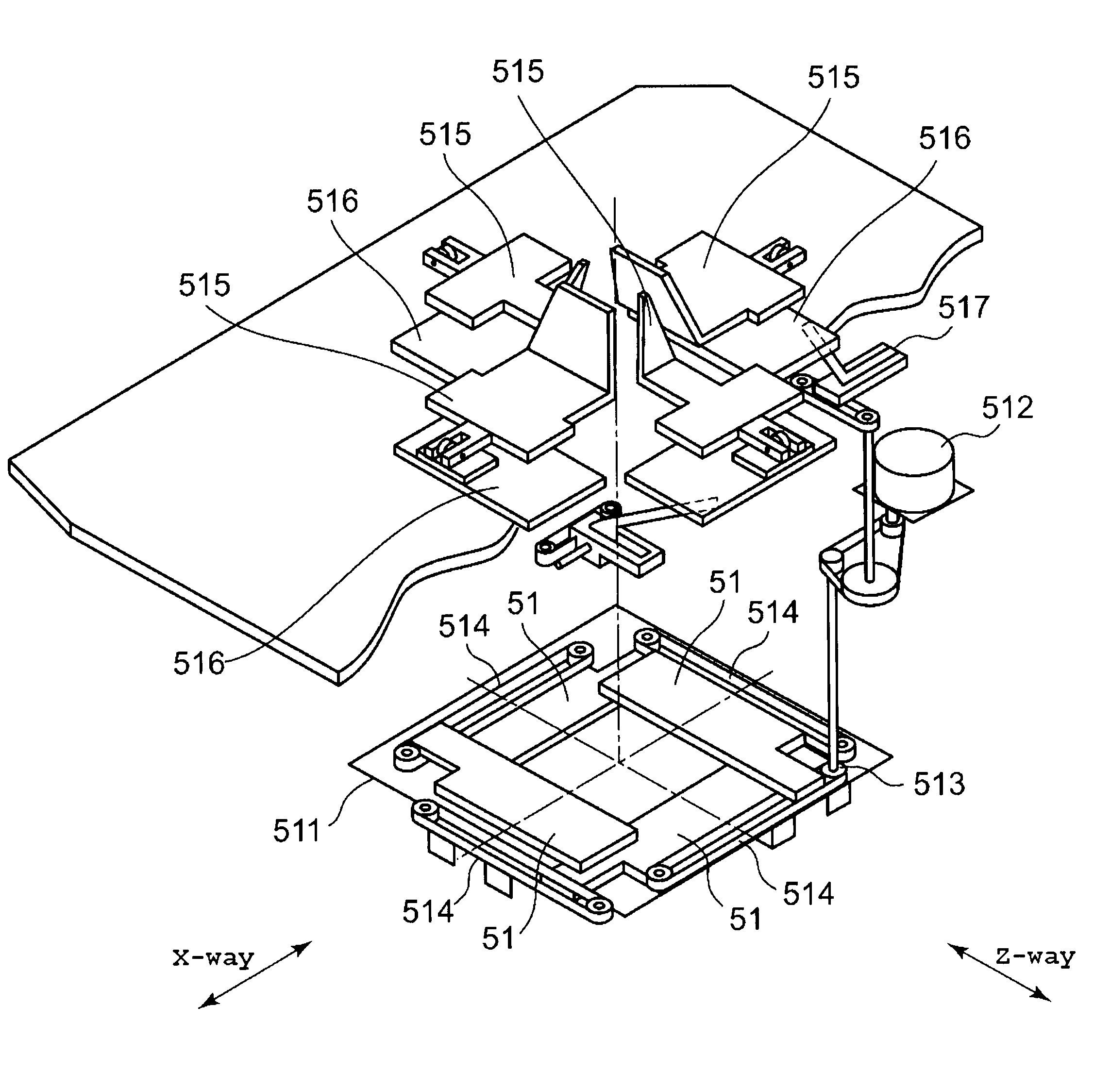
[0161]FIG. 20 is a conceptual diagram of the X-ray diagnostic apparatus according to a third embodiment. As shown in FIG. 20, C-arm 14 (imaginary line in FIG. 20) is supported to the retention feature rotatably. X-ray tube 3 and diaphragm blade unit 51 are installed on part of C-arm 14. X-ray detector 4 is installed on other edges of C-arm 14.

[0162]As shown in FIG. 20, C-arm 14 (chain line in FIG. 20) rotates, and the exposure field 4a approaches the test object of subject. When the center of...


PUM


Abstract

When distance compute unit 81 received the instruction of the moving destination at the center of the exposure field 4a from center transfer operation unit 74, calculates the moving amount. Operating information processing unit 8 sends beam-limiting control unit 62 the calculated moving amount. Upside beam-limiting control unit 63 to right side beam-limiting control unit of beam-limiting control unit 62 makes the moving amount at the center of the exposure field 4a prescribed-times ((H1/H2) times in FIG. 3), calculates the moving amount of each diaphragm blade unit 51 in the upper part, the lower side, and the left part and the right part respectively.

Description

CROSS-REFERENCE TO RELATED APPLICATIONS[0001]This application is based upon and claims the benefit of priority from prior Japanese Patent Application No. 2007-247206, filed Sep. 25, 2007, the entire contents of which are incorporated herein by reference.BACKGROUND OF THE INVENTION[0002]1. Field of the Invention[0003]The present invention relates to an X-ray diagnostic apparatus, and particularly relates to setting of a radiation field of X-rays.[0004]2. Description of the Related Art[0005]Traditional X-ray diagnostic apparatus generally comprises a tabletop, an X-ray tube, and an X-ray detector. The tabletop is put a subject, the X-ray tube irradiates X-rays, and the X-ray detector detects X-rays that permeate the subject. The X-ray tube and X-ray detector are arranged on both sides of the tabletop. X-ray detecting elements are arranged to the detection range of the X-ray detector that detects X-rays.[0006]A retention feature maintains the X-ray tube. The X-ray tube is composed mova...

Claims


Application Information

Patent Timeline
IPC IPC(8): G21K5/10G03B42/02
CPCA61B6/06A61B6/04
Inventor KOSUGI, NORIMITSU
Owner TOSHIBA MEDICAL SYST CORP
Why Eureka
Try Eureka