
Muffler for an exhaust gas system

a technology of exhaust gas and muffler, which is applied in the direction of machines/engines, mechanical equipment, gas passages, etc., can solve the problems of increasing the pressure in the exhaust system upstream from the muffler, increasing the pressure can have a considerable negative effect on the performance and efficiency of the internal combustion engine in certain operating states, and adding-on operation may be associated with additional noise emission into the environment, so as to improve the silencing effect and be inexpensive to manufactur

Active Publication Date: 2007-03-01
PUREM GMBH
View PDF21 Cites 29 Cited by
  • Summary
  • Abstract
  • Description
  • Claims
  • Application Information

AI Technical Summary

Benefits of technology

[0004] The present invention provides an embodiment of a muffler which has an improved silencing effect, and which is inexpensive to manufacture.
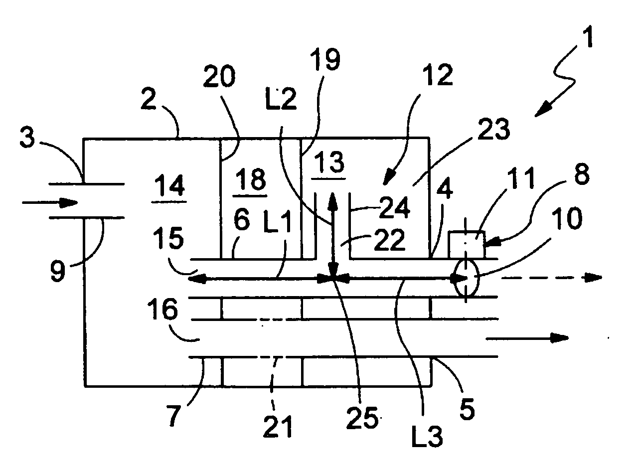
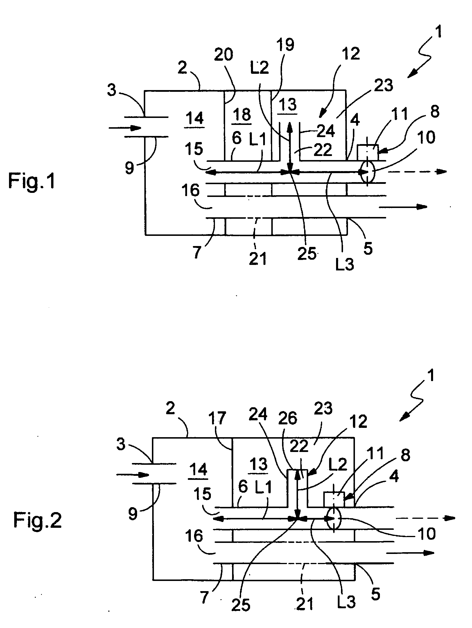
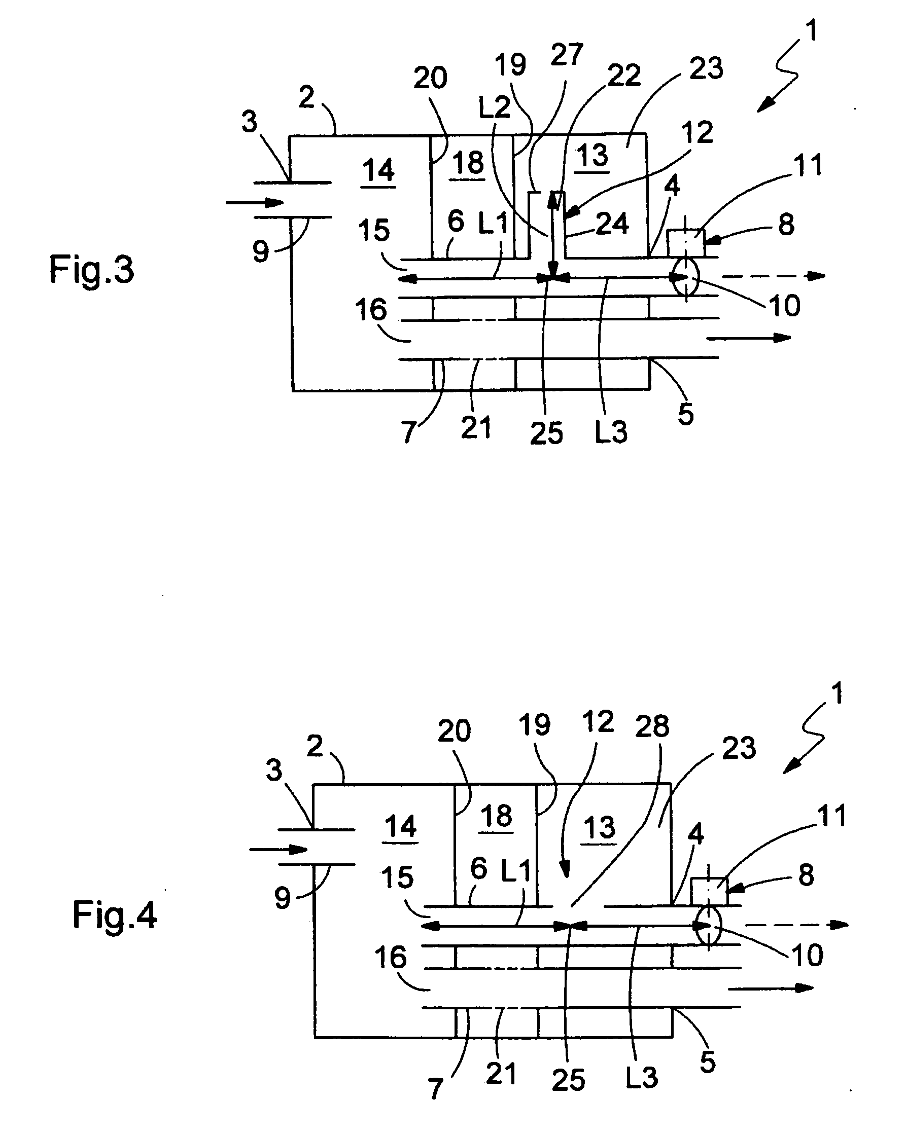
[0005] The present invention is based on the general idea of acoustically coupling a switchable pipe of the muffler to a damping system in such a way that, on the one hand, the damping system is active when the pipe is opened and also when it is closed, i.e., it manifests its respective silencing effect in both cases, and on the other hand, it has a different damping characteristic when the pipe is opened than when it is closed. Due to this design, the switchable pipe forms a component of an effective damping system even in the closed state, changing its damping characteristics when the pipe is opened but remaining active. It is especially advantageous that the flow resistance of the muffler can be controlled with the help of a control device on the one hand while on the other hand the damping characteristics of the muffler can be varied. It is also especially advantageous that the damping system that is connected to the switchable pipe can be designed so that in both switch states, the interfering frequencies and / or the most interfering frequency ranges are suppressed.

Problems solved by technology

In the case of mufflers, generally the problem is that gas flows against a flow resistance through the muffler, thus creating an increase in pressure in the exhaust system upstream from the muffler.
This increase in pressure can have a considerable negative effect on the performance and efficiency of the internal combustion engine in certain operating states.
However, it has been found that this adding-on operation may be associated with additional noise emission into the environment because the silencing effect of the muffler is fundamentally optimized with regard to operating states having a low exhaust flow.

Method used


Image

  • Muffler for an exhaust gas system
  • Muffler for an exhaust gas system
  • Muffler for an exhaust gas system

Examples


Embodiment Construction

[0010] It is to be understood that the figures and descriptions of the present invention have been simplified to illustrate elements that are relevant for a clear understanding of the present invention, while eliminating, for purposes of clarity, many other elements found in typical mufflers. However, because such elements are well known in the art, and because they do not facilitate a better understanding of the present invention, a discussion of such elements is not provided herein. The disclosure herein is directed to all such variations and modifications known to those skilled in the art.

[0011] In accordance with FIGS. 1 through 6, muffler 1 comprises a housing 2 having at least one exhaust inlet and at least one exhaust outlet. In the illustrated embodiment(s), housing 2 has one exhaust inlet 3 and two exhaust outlets 4, 5. Muffler 1 is provided for installation in an exhaust gas system (not shown) of an internal combustion engine (also not shown), the internal combustion engi...


PUM


Abstract

The invention relates to a muffler for an exhaust system of an internal combustion engine, consisting a housing having at least one exhaust inlet and at least one exhaust outlet and having at least two pipes at the inlet end or at the outlet end, at least one of which is switchable by a control device at least between an open state and a closed state and is acoustically coupled to a silencer system, such that the silencer system is active when the switchable pipe is opened as well as when it is closed and has a different damping characteristic when the switchable pipe is opened than when the switchable pipe is closed.

Description

FIELD OF THE INVENTION [0001] The present invention relates generally to a muffler for an exhaust system of an internal combustion engine, in particular in a motor vehicle. BACKGROUND OF THE INVENTION [0002] A muffler generally includes a housing having at least one exhaust inlet and at least one exhaust outlet. Pipes may protrude into the housing on the inlet end and on the outlet end, and it is essentially possible to provide at least two pipes leading in parallel into the housing and / or out of the housing on the inlet end or the outlet end. In the case of mufflers, generally the problem is that gas flows against a flow resistance through the muffler, thus creating an increase in pressure in the exhaust system upstream from the muffler. This increase in pressure can have a considerable negative effect on the performance and efficiency of the internal combustion engine in certain operating states. It is therefore fundamentally possible to open and close at least one of the parallel...

Claims


Application Information

Patent Timeline
Patent Type & Authority Applications(United States)
IPC IPC(8): F01N1/00F01N1/02
CPCF01N1/003F01N1/023F01N1/163F01N1/166F01N2470/14F01N2470/16
Inventor HOERR, MICHAPOMMERER, MICHAEL
Owner PUREM GMBH
Learn More