
Foldable, lockable control surface and method of using same

a control surface and lockable technology, applied in the direction of weapons, self-propelled projectiles, projectiles, etc., can solve the problems of affecting the safety of passengers, so as to achieve the effect of limiting flutter

Inactive Publication Date: 2007-03-01
LOCKHEED MARTIN CORP
View PDF15 Cites 21 Cited by
  • Summary
  • Abstract
  • Description
  • Claims
  • Application Information

AI Technical Summary

Benefits of technology

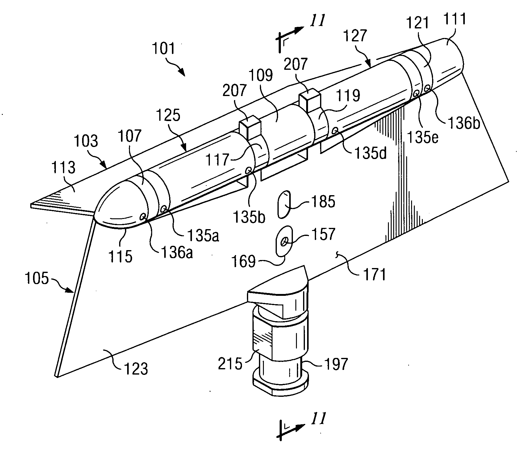
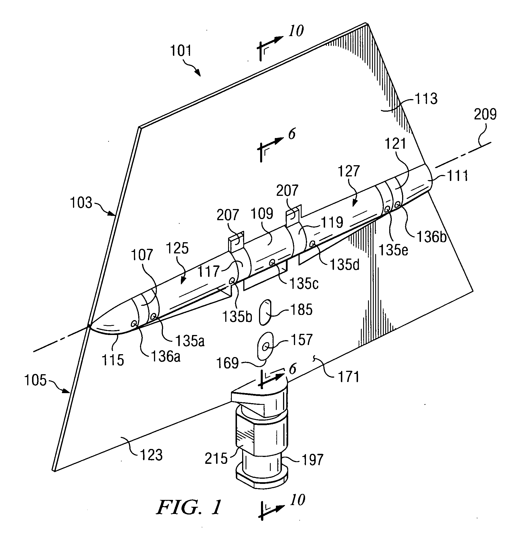
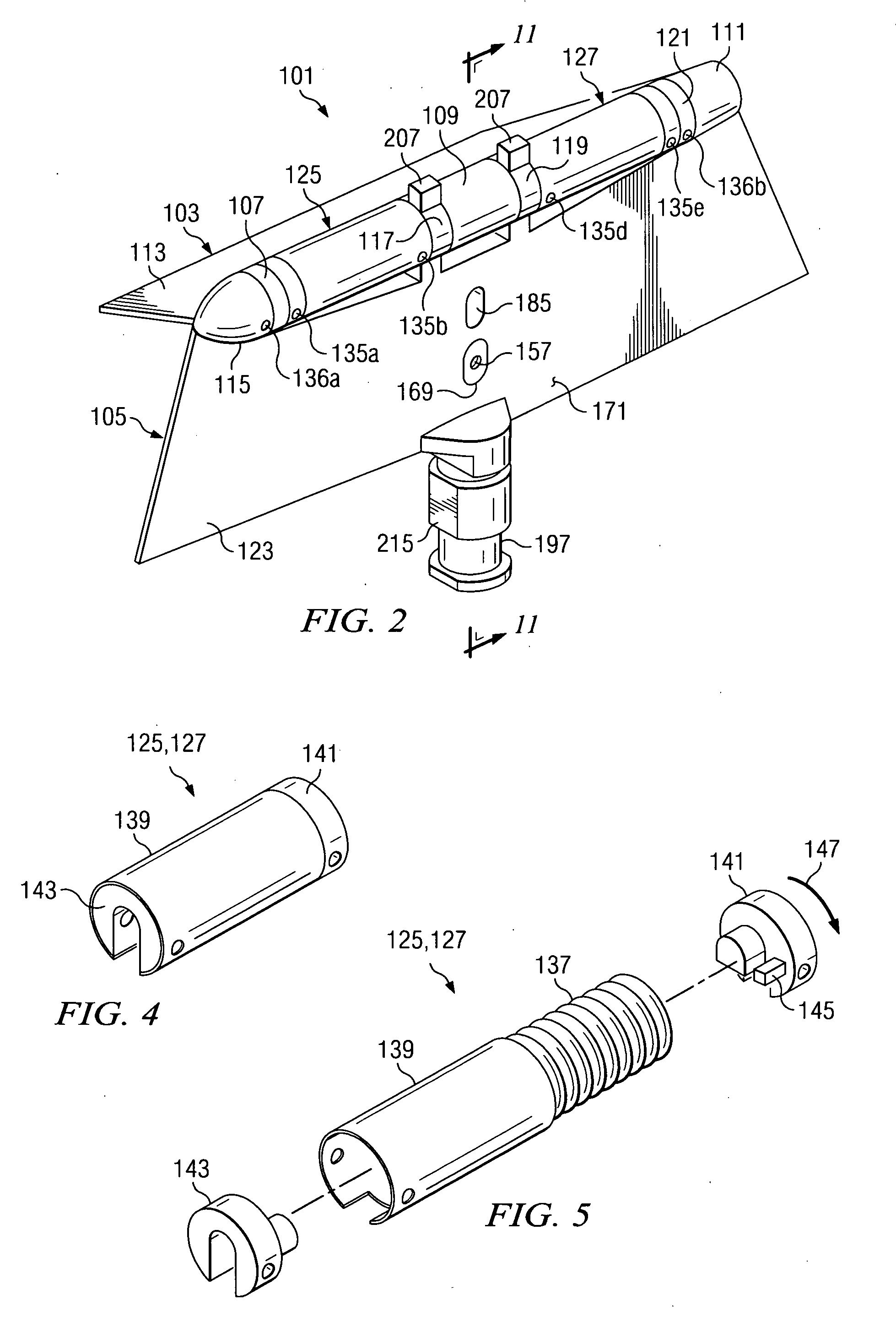
[0018] The present invention provides significant advantages, including: (1) aerodynamic loads exerted on the outer control surface member are efficiently transmitted to the inner control surface member via the hinge attachment; (2) the locking mechanism of the present invention limits flutter in the outer control surface member during flight; and (3) the locking mechanism of the present invention requires no externally-provided motive force to operate.

Problems solved by technology

In many cases, the mechanism is released from the vehicle's body after the control surfaces are unfolded, thus presenting a potential debris problem for the surrounding environment.
These restraint devices also pose problems for the surrounding environment, as they may impact the launch platform or other surrounding equipment.
Such mechanisms are complex and can present hazardous situations if improperly activated.
Mechanisms used to retain control surfaces in their unfolded, deployed configurations also use external power sources, pyrotechnics, or chemical activation for actuating the retention mechanisms, with similar problems as noted above.
Generally, such close dimensional tolerances require expensive, time consuming machining or other manufacturing processes.

Method used


Image

  • Foldable, lockable control surface and method of using same
  • Foldable, lockable control surface and method of using same
  • Foldable, lockable control surface and method of using same

Examples


Embodiment Construction

[0034] Illustrative embodiments of the invention are described below. In the interest of clarity, not all features of an actual implementation are described in this specification. It will of course be appreciated that in the development of any such actual embodiment, numerous implementation-specific decisions must be made to achieve the developer's specific goals, such as compliance with system-related and business-related constraints, which will vary from one implementation to another. Moreover, it will be appreciated that such a development effort might be complex and time-consuming but would nevertheless be a routine undertaking for those of ordinary skill in the art having the benefit of this disclosure.

[0035] The present invention represents a foldable, lockable control surface for an airborne or waterborne vehicle. Such vehicles include, but are not limited to, missiles, rockets, drones, projectiles, torpedoes, and the like, which are adapted to travel through a medium, wheth...


PUM


Abstract

A foldable, lockable control surface includes an inner control surface member and an outer control surface member hingedly attached along a hinge line to the inner control surface member. The control surface further includes a biasing assembly disposed on the hinge line, the outer control surface being operably associated with the inner control surface member and the outer control surface member and a locking mechanism operably associated with the outer control surface member. An apparatus includes a foldable, lockable control surface having a control surface actuation shaft extending therefrom and a control surface actuator having a control surface actuator output port in which the control surface actuation shaft is received. The apparatus further includes means for clocking the control surface actuation shaft in the control surface actuator output port.

Description

[0001] The U.S. Government has a paid-up license in this invention and the right in limited circumstances to require the patent owner to license others on reasonable terms as provided for by the terms of contract number DAAH01-03-C-0164 awarded by the United States Army.BACKGROUND [0002] 1. Field of the Invention [0003] The present invention relates to control surfaces for an airborne or waterborne vehicle. In particular, the present invention relates to a foldable, lockable control surface for an airborne or waterborne vehicle and a method of using the control surface. [0004] 2. Description of Related Art [0005] Airborne and waterborne vehicles are often used to deliver a payload to a target location or to carry the payload over a desired area. For example, rockets, missiles, torpedoes, drones, projectiles, and other such vehicles may be used in combat situations to deliver explosive warheads, kinetic energy penetrators, or other payloads to destroy or disable the target. Surveilla...

Claims


Application Information

Patent Timeline
Patent Type & Authority Applications(United States)
IPC IPC(8): F42B10/00
CPCF42B10/64F42B10/14
Inventor HELLIS, NEIL C.
Owner LOCKHEED MARTIN CORP
Learn More