
Closing device for drawers

a closing device and drawer technology, applied in drawers, furniture parts, domestic applications, etc., can solve the problems of undesirable noise, wear of pivoting and spring components, etc., and achieve the effect of eliminating wear and noise, reducing maintenance costs, and simplifying structur

Inactive Publication Date: 2007-03-01
KNAPE & VOGT MFG
View PDF52 Cites 49 Cited by
  • Summary
  • Abstract
  • Description
  • Claims
  • Application Information

AI Technical Summary

Benefits of technology

[0016] Thus, the present invention presents an alternative to prior art closing devices for drawers. The present invention also simplifies the structure to permit smoother and quieter operation of a self-closing drawer slide. The present invention eliminates the wear and noise typically associated with tiltable or pivotable latching members, as well as much of the complexity and noise associated with prior art devices which utilize a latching member that moves in multiple directions in association with a slot in a planar wall.

Problems solved by technology

While such tiltable or pivotable latching member and pin assemblies function for their intended purpose, they present potential problems in regard to wear of the pivoting and spring components, noise associated with the pivoting components as they move from one position to another, as well as noise associated with the spring as it is bent or shifts within its mounting relationship with the latching member or housing as the latching member tilts, pivots and / or translates.
This stretching may occur with the spring having to bend or interfere with housing walls due to the path of the slider.
Indeed, this permits a spring to be used in tension to avoid the need for a pin or rod through the spring or containment walls, either of which prevents buckling via contact with the coils of the spring as it moves, but which also tends to impart undesirable noise due to the contact necessary to prevent the buckling.

Method used


Image

  • Closing device for drawers
  • Closing device for drawers
  • Closing device for drawers

Examples


Embodiment Construction

[0034] Referring generally to FIGS. 1-9B, it will be appreciated that the drawer closing device of the present invention generally may be embodied within numerous configurations within a device that may be incorporated into a self-closing drawer slide.

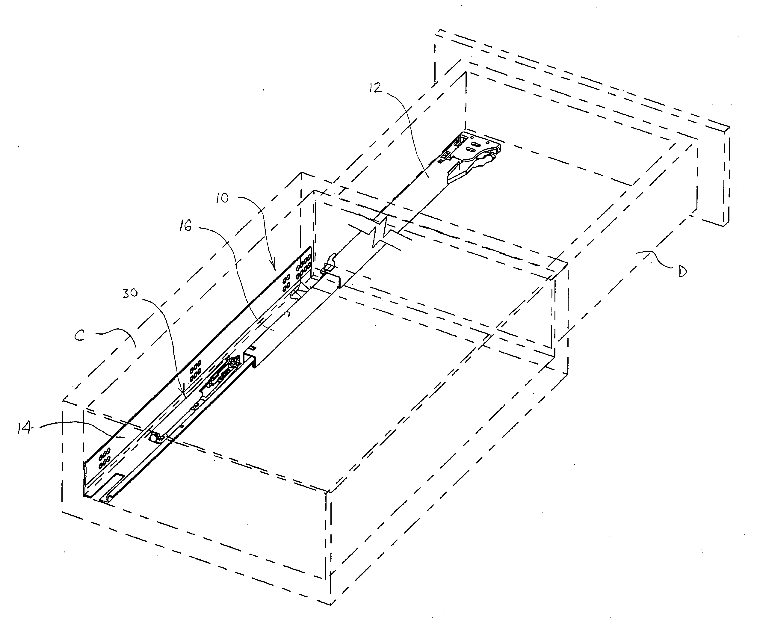
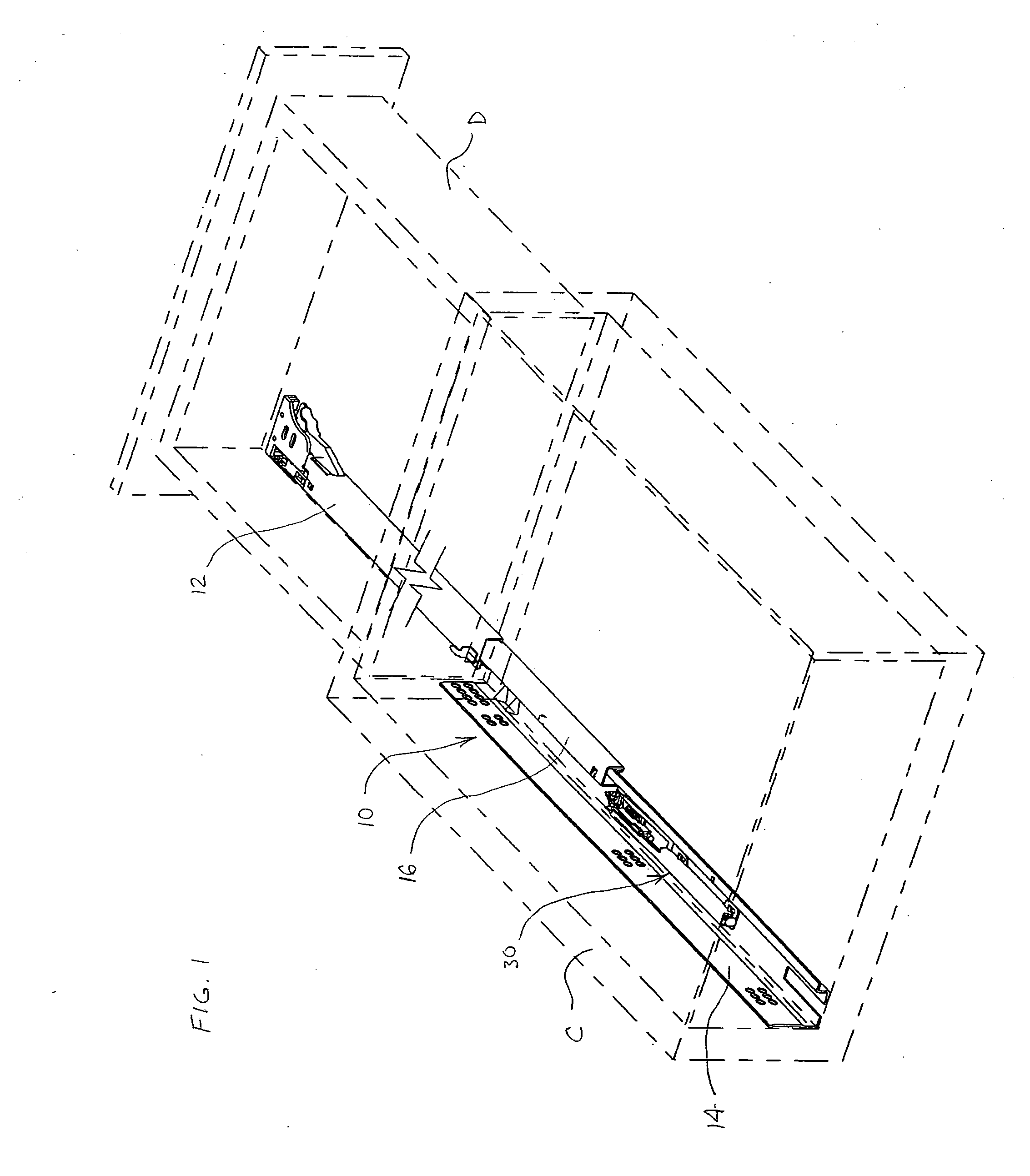
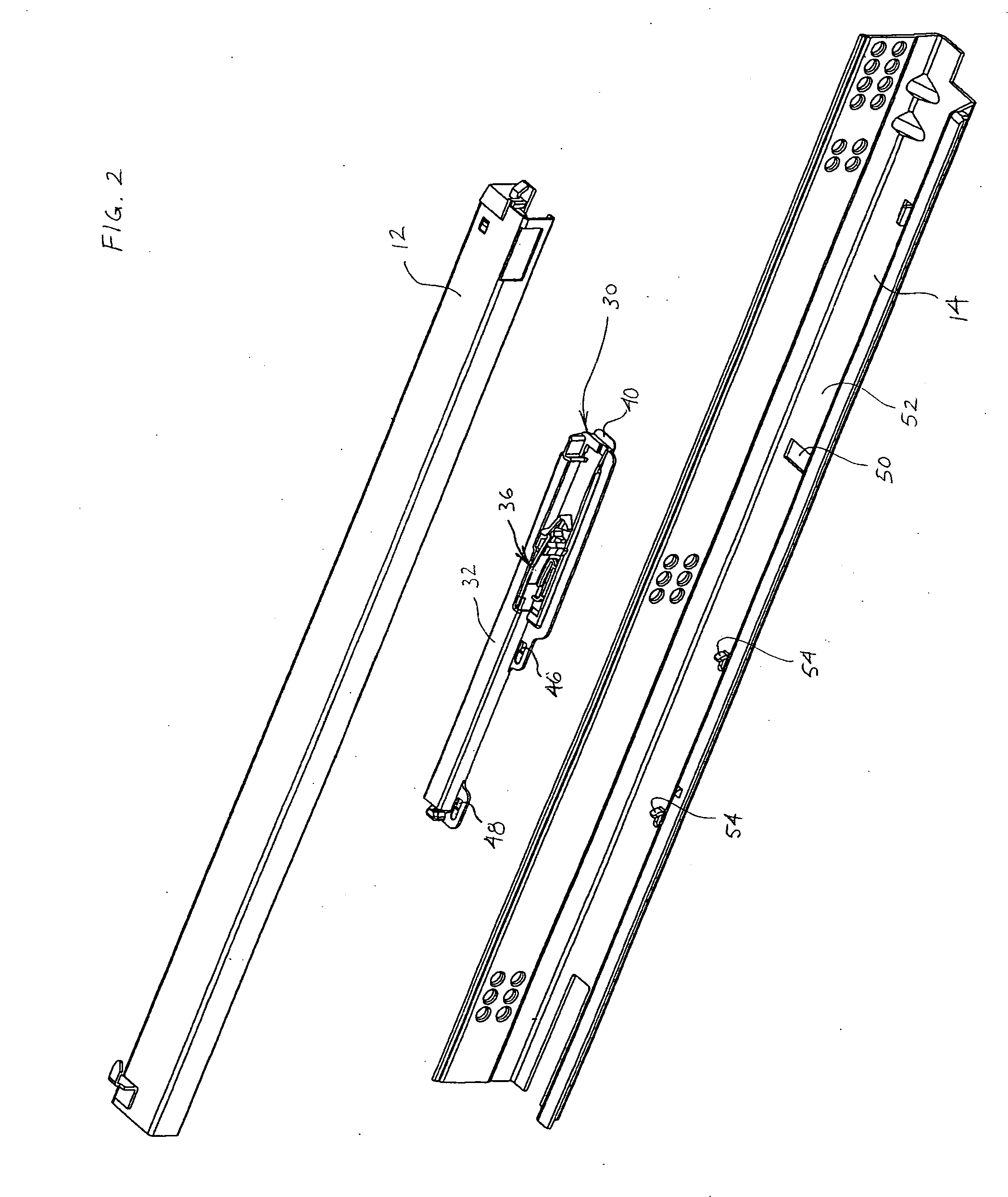
[0035] Referring to a preferred embodiment in FIGS. 1-7, a drawer closing device 10 is shown incorporated into the form of a self-closing drawer slide. The drawer closing device 10 is shown having a first drawer slide member 12 for attachment by conventional means to a drawer D (shown in phantom), a second drawer slide member 14 for attachment by conventional means to a cabinet C (shown in phantom), and third drawer slide member 16 slidably engaging the first and second drawer slide members 12 and 14, respectively. Use of third drawer slide member 16 permits greater extension of drawer D from the face of cabinet C when in the fully opened position (as shown), and often drawer slides of this type are referred to as full extension drawe...


PUM


Abstract

A closing device for drawers, the device having a housing with a holding notch and a slider having a resilient latching arm that is bendable to engage the holding notch, as well as a spring that engages the housing and the slider to urge the slider to a rearward position relative to the housing. The resilient latching arm has a slot adapted to receive a pin, whereby as the drawer is moved from its closed position, the relative movement of the pin advances the slider to a position where the resilient latching arm engages the holding notch and the drawer is free to mover further outward without influence of the closing device. As the drawer is moved rearward toward its closed position, the relative movement of the pin will cause it to engage the slot in the resilient latching arm, further causing it to release from the holding notch and to be urged by the spring to move the drawer toward a closed position.

Description

BACKGROUND OF THE INVENTION [0001] 1. Field of the Invention [0002] The present invention generally relates to closing devices for drawers, often incorporated into drawer slides otherwise known as self-closing drawer slides. Such drawer slides tend to be used in articles of furniture, such as cabinets, for assisting in moving a drawer to a fully closed position within the cabinet body. [0003] 2. Discussion of the Prior Art [0004] Articles of furniture having drawers, such as cabinets, typically include drawer slides for mounting the drawers to the cabinet and for providing a way to move the drawer between a fully closed position within the cabinet body to an open position with the drawer extending outward from the cabinet body. Standard drawer slides tend to be mounted in pairs, with one on each of the left and right outer sides of the drawer. In such configuration, one drawer slide member is attached to the cabinet body and a second drawer slide member is attached to the outer side...

Claims


Application Information

Patent Timeline
Patent Type & Authority Applications(United States)
IPC IPC(8): A47B88/04
CPCA47B88/047A47B88/467
Inventor HOFFMAN, KEITH A.
Owner KNAPE & VOGT MFG
Learn More