Electronic pen having an ultrasonic wave controller

an electronic pen and ultrasonic wave technology, applied in the field of electronic pen, can solve the problems of inability to accurately detect the coordinates, the ultrasonic wave pulse that is to be detected cannot be correctly recognized, and the canopy will increase the size of the ultrasonic wave sensor, so as to achieve the effect of improving accuracy

Inactive Publication Date: 2007-03-01
NEC DISPLAY SOLUTIONS LTD
View PDF14 Cites 18 Cited by
  • Summary
  • Abstract
  • Description
  • Claims
  • Application Information

AI Technical Summary

Benefits of technology

[0010] An object of the present invention is to provide an electronic pen, an electronic whiteboard system, and a projector system that are able to prevent the reflection of an ultrasonic wave that is transmitted from an ultrasonic wave transmitter, in order to improve accuracy with which the coordinate of an electronic pen is calculated, particularly for an electronic pen for which it is difficult to provide an ultrasonic wave sensor with directivity.

Problems solved by technology

As a result, an electronic whiteboard system, which detects the coordinate of a pen under the condition that an ultrasonic wave directly reaches the ultrasonic wave sensor from the ultrasonic wave transmitter along a straight line, cannot detect the coordinate accurately due to the reflected wave.
For example, if an ultrasonic wave that is reflected reaches the ultrasonic wave sensor with delay, and, at the same time, the next ultrasonic wave that is transmitted later reaches the ultrasonic wave sensor along a straight line, then there is the possibility that an ultrasonic wave pulse that is to be detected cannot be recognized correctly.
A similar problem may also occur when a pulse of ultrasonic wave reaches the ultrasonic wave sensor along a straight line, then the ultrasonic wave that is reflected reaches the ultrasonic wave sensor, and then the next pulse reaches the ultrasonic wave sensor along a straight line.
However, a canopy will increase the size of the ultrasonic wave sensor, as well as the cost.
On the other hand, in an electronic whiteboard system or a projector system using an ultra-short focal length projector, as shown in FIG. 5, it is difficult to provide an ultrasonic wave sensor with directivity by using a canopy, because the ultrasonic wave sensor is arranged away from the screen, or the projection surface.
In an electronic whiteboard system, it is difficult to provide an ultrasonic wave sensor with directivity for a specific direction, because the distance between the projector and the projection surface differs depending on the size of the image that is to be projected.

Method used


Image

  • Electronic pen having an ultrasonic wave controller
  • Electronic pen having an ultrasonic wave controller
  • Electronic pen having an ultrasonic wave controller

Examples


first embodiment

[0031] (First Embodiment)

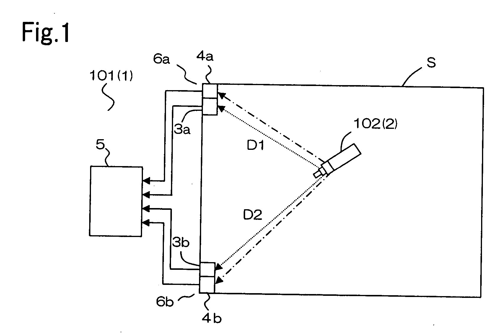
[0032] An electronic whiteboard system of the present invention is similar to a conventional electronic whiteboard system except for the configuration of the electronic pen. Specifically, referring to FIG. 1, electronic whiteboard system 1 has electronic pen 2, at least two ultrasonic wave sensors 3a, 3b, infrared ray sensors 4a, 4b, and coordinate calculator 5. Ultrasonic wave sensors 3a, 3b are arranged apart from each other at corners 6a, 6b on the left side of writing surface S, on which information is written by electronic pen 2. Infrared sensors 4a, 4b for receiving an infrared ray are arranged adjacent to respective ultrasonic wave sensors 3a, 3b on writing surface S. Coordinate calculator 5, which is connected to ultrasonic wave sensors 3a, 3b and infrared ray sensors 4a, 4b, calculates distance D1 between corner 6a and electronic pen 2 based on the difference between the time at which an infrared ray is received by infrared ray sensor 4a and the tim...

second embodiment

[0039] (Second Embodiment)

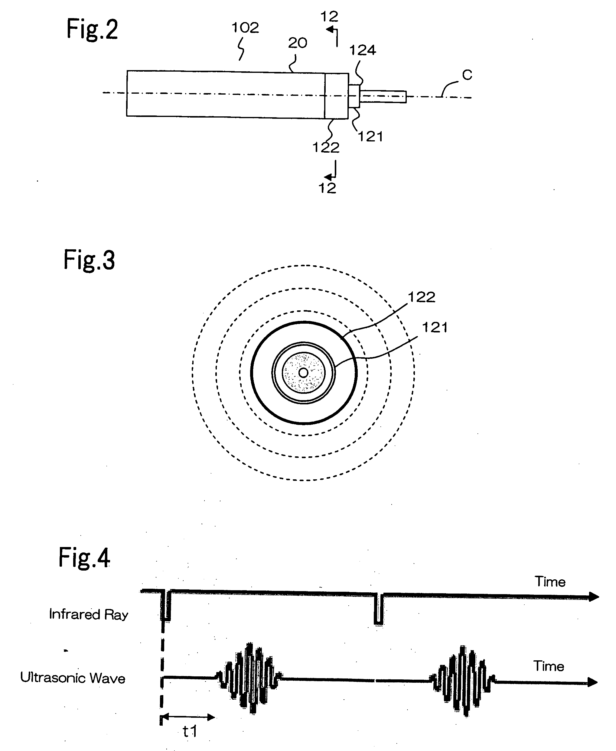
[0040] The second embedment is similar to the first embodiment except for the configuration of the ultrasonic wave transmitters and the controller. FIG. 10 is a cross-sectional view of an electronic pen near the tip portion, viewed from the tip of the writing side. One ultrasonic wave transmitter 71 is provided around longitudinal axis C near the tip of the writing side of electronic pen 7. In the illustrated embodiment, ultrasonic wave transmitter 71 includes vibrator 76 that is arranged coaxially with longitudinal axis C of electronic pen 7 and vibrating plate 77 that surrounds vibrator 76.

[0041]FIG. 11 is a block diagram of major components of the electronic pen which are related to the transmission of an ultrasonic wave. Controller 73 includes sensor detecting section 73a for detecting the orientation of electronic pen 7 that is directed at ultrasonic wave sensors 3a, 3b, and ultrasonic wave limiter 73b. Sensor detecting section 73a has a configuration...

third embodiment

[0044] (Third Embodiment)

[0045] The third embodiment is similar to the second embodiment except for the configuration of the controller of the electronic pen. Specifically, the third embodiment is different from the second embodiment in that it utilizes gravity to press the pressing bodies. FIG. 14 is a side view of the tip portion of an electronic pen illustrating the configuration around an ultrasonic wave transmitter. Ultrasonic wave transmitter 91 is provided around longitudinal axis C near write side tip 94 of electronic pen 9. The controller includes a plurality of pressing bodies 98a-98d, which are arranged around ultrasonic wave transmitter 91 at intervals of 90°, and supporting members 99a-99d for supporting pressing bodies 98a-98d. Pressing body 98d and supporting member 99d are omitted in the drawing. Supporting members 99a-99d have pendulums, and pressing bodies 98a-98d are free to move in the vertically downward direction by virtue of gravity. Since four pressing bodies...


PUM


Abstract

The present invention aims to provide an electronic pen that is able to prevent the reflection of an ultrasonic wave. An electronic pen according to the present invention has: a housing having a longitudinal axis and a write side tip along the longitudinal axis; at least an ultrasonic wave transmitter, the ultrasonic wave transmitter being arranged near the write side tip of the housing; and a controller for detecting a sensor orientation and for controlling transmission of the ultrasonic wave. The sensor orientation is an index that shows a rotational orientation of the housing about the longitudinal axis, the rotational orientation being directed at an ultrasonic wave sensor for receiving the ultrasonic wave that is transmitted from the ultrasonic wave transmitter. The controller selectively activates a part of the ultrasonic wave transmitter such that the ultrasonic wave is transmitted from the orientation which is directed to the sensor orientation.

Description

[0001] The present application is based on, and claims priority from, J.P. Application No. 2005-241297, filed Aug. 23, 2005, the disclosure of which is hereby incorporated by reference herein in its entirety. BACKGROUND OF THE INVENTION [0002] 1. Field of the Invention [0003] The present invention relates to an electronic pen, an electronic whiteboard system, and a projector system, and in particular, relates to a mechanism of an electronic pen for transmitting an ultrasonic wave. [0004] 2. Description of the Related Art [0005] An electronic whiteboard system using an ultrasonic wave and an infrared ray is widely used. FIG. 1 is a schematic diagram illustrating the configuration of a conventional electronic whiteboard system. Electronic whiteboard system 101 includes electronic pen 102, ultrasonic wave sensors 3a, 3b, infrared ray sensors 4a, 4b, and coordinate calculator 5 that is connected to ultrasonic wave sensors 3a, 3b and infrared ray sensors 4a, 4b. Ultrasonic wave sensors 3...

Claims


Application Information

Patent Timeline
Patent Type & Authority Applications(United States)
IPC IPC(8): G09G5/00
CPCG06F3/043G06F3/03545
Inventor TOMIYA, SHU
Owner NEC DISPLAY SOLUTIONS LTD
Why Eureka
Try Eureka