
System and Method for Premises End Crosstalk Compensation

a crosstalk compensation and premises technology, applied in the field of communication, can solve problems such as mismatch in mutual coupling capacitance, and achieve the effect of reducing or eliminating mismatch

Inactive Publication Date: 2007-03-01
BREMER GORDON +1
View PDF6 Cites 44 Cited by
  • Summary
  • Abstract
  • Description
  • Claims
  • Application Information

AI Technical Summary

Benefits of technology

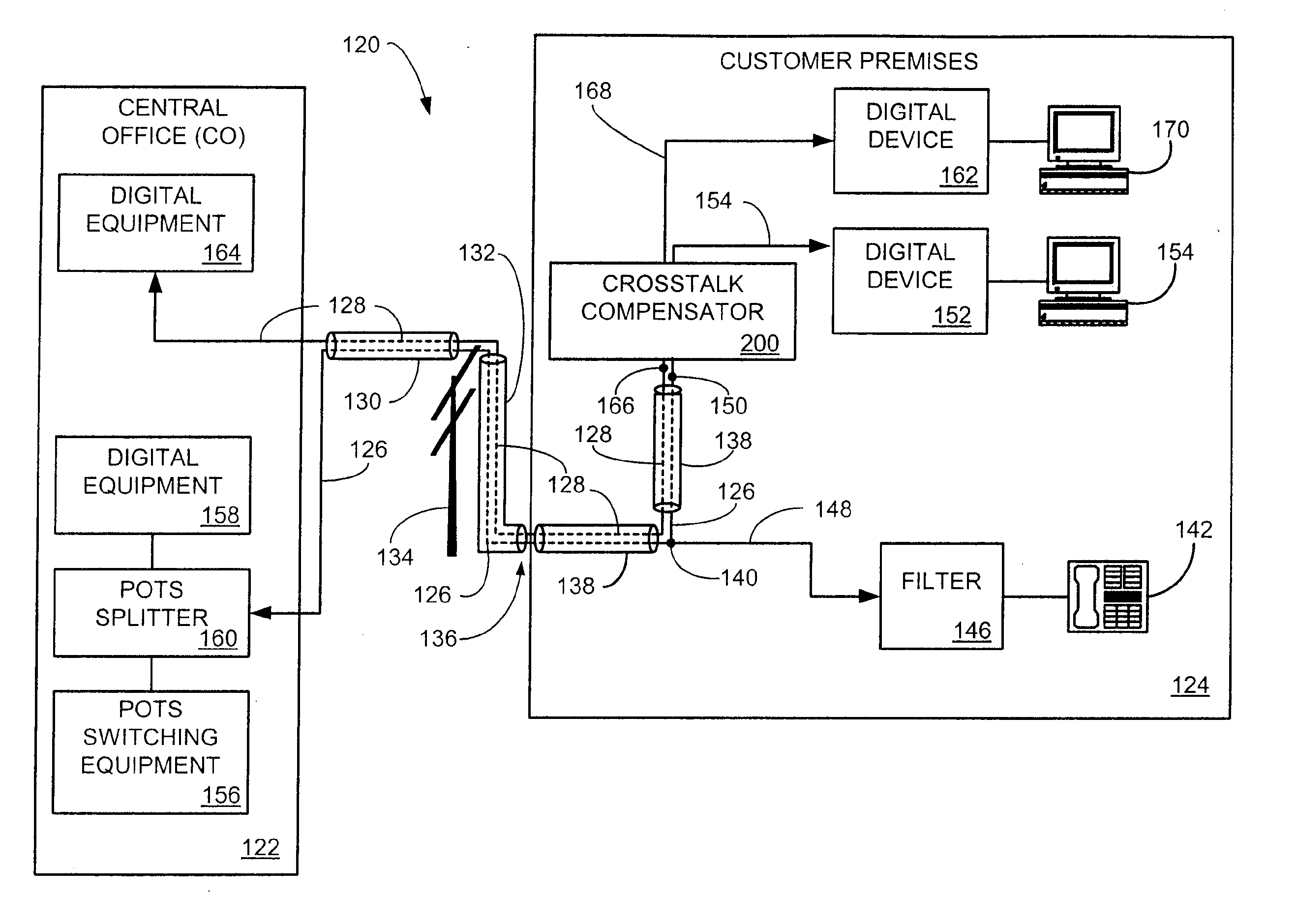
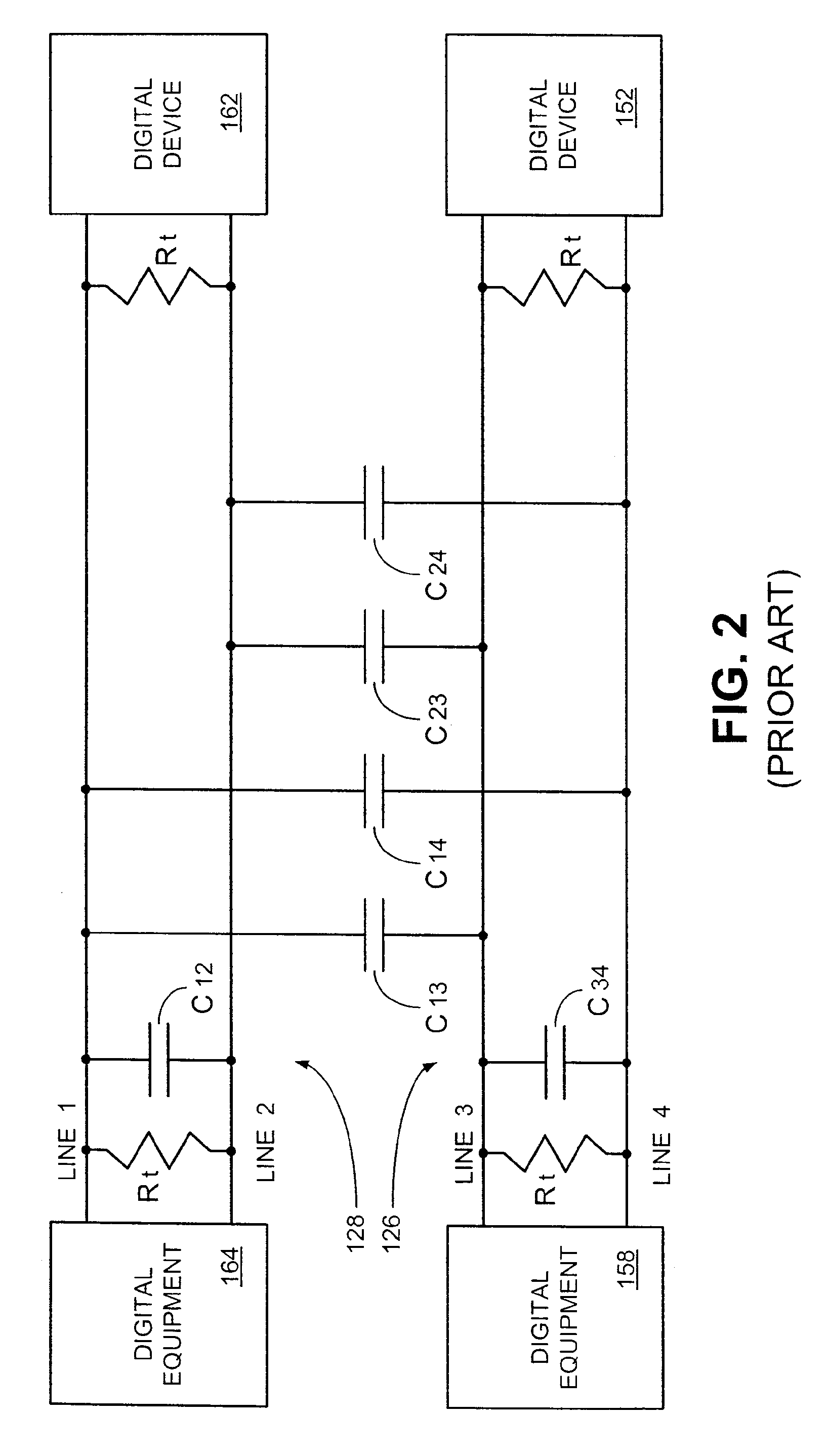
[0030] The present invention provides a crosstalk compensator system and method for the compensation of mismatches in mutual coupling capacitances between adjacent parallel subscriber loops. The aforementioned mismatch in mutual coupling capacitance may arise in the customer's premises wiring system which may consist of the drop cable, cable run and / or receiver cable. Mismatches in the mutual coupling capacitances in the customer's premises wiring system may give rise to undesirable levels of premises end crosstalk (PEXT) interference for which the preferred embodiment of the crosstalk compensator has been designed to mitigate by providing a system and method for the addition of compensating capacitors such that the mismatch is reduced or eliminated.
[0031] The preferred embodiment of the crosstalk compensator has two groups, each group having three compensating capacitors. The compensating capacitors have switches such that, when connected in parallel with two subscriber loops that have a mismatch in their mutual coupling capacitances, one of more of the compensating capacitors may be connected such that the mismatch is reduced or eliminated, thereby reducing or eliminating the undesirable PEXT interference.
[0035] The crosstalk compensator can be conceptualized as providing one or more methods for reducing or eliminating PEXT interference between adjacent parallel subscriber loops. In accordance with one method of the invention, the method may be broadly summarized by the following steps: connecting a compensating capacitor group to a pair of conductors; detecting said at least one mismatch between said plurality of mutual coupling capacitances; selecting at least one compensating capacitor residing in the compensating capacitor group; and switching the at least one compensating capacitor such that the compensating capacitor is connected in parallel with the pair of conductors to reduce the mismatch.

Problems solved by technology

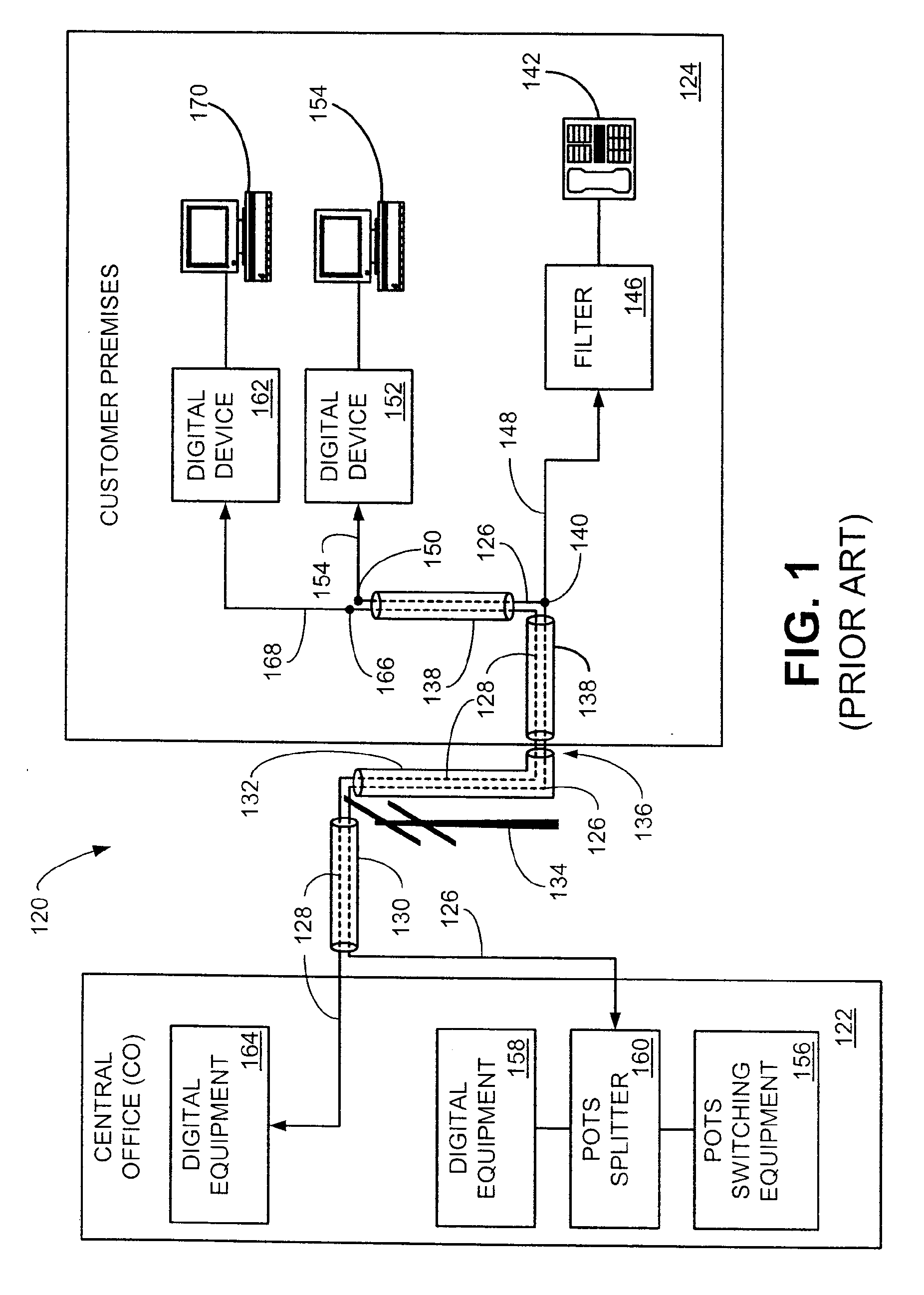
The aforementioned mismatch in mutual coupling capacitance may arise in the customer's premises wiring system which may consist of the drop cable, cable run and / or receiver cable.

Method used


Image

  • System and Method for Premises End Crosstalk Compensation
  • System and Method for Premises End Crosstalk Compensation
  • System and Method for Premises End Crosstalk Compensation

Examples


first alternative embodiment

IV. First Alternative Embodiment

[0077]FIG. 7 shows an alternative embodiment of a crosstalk compensator in accordance with the present invention, which is generally denoted by reference numeral 201. The crosstalk compensator 201 contains only one parallel grouping of compensating capacitors CC1, CC2 and CC3, denoted as CX. During installation of the crosstalk compensator 201, the installer would first determine if there was any significant mismatch between mutual coupling capacitances C13 and C14 (FIG. 5) which would cause undesirable levels of PEXT interference. If there was a significant degree of mismatch between C13 and C14, the installer would determine which was the smaller of C13 and C14. The installer would then connect the crosstalk compensator 201 to the appropriate lines such that undesirable levels of PEXT interference induced from subscriber loop 126 onto line 1 of loop 128 would be mitigated or eliminated. For example, if the installer determined that C13 was less than...

second alternative embodiment

V. Second Alternative Embodiment

[0082] A second alternative embodiment of a crosstalk compensator in accordance with the present invention is illustrated in FIG. 8 and generally denoted by reference numeral 202. This alternative embodiment of the crosstalk compensator 202 is similar to the first alternative embodiment of the crosstalk compensator 201 (FIG. 7) in that only a single group of compensating capacitors CC1, CC2 and CC3 are provided, denoted as CX. With this alternative embodiment of the crosstalk compensator 202, the installer would determine if there was a mutual coupling capacitance mismatch as described hereinabove and then select the compensating capacitors CC1, CC2 and / or CC3 by closing switches S1, S2 and / or S3, respectively such that CX is added to the desired mutual coupling capacitance in the above-described manner to eliminate any undesirable significant PEXT interference.

[0083] This alternative embodiment of the crosstalk compensator 202 has two additional lin...

third alternative embodiment

VI. Third Alternative Embodiment

[0085]FIG. 9 illustrates a third alternative embodiment of the crosstalk compensator 203. This third alternative embodiment of the crosstalk compensator 203 is similar to the second alternative embodiment of the crosstalk compensator 202 (FIG. 8) with the addition of a processor-based line selection switch system. This alternative embodiment of the crosstalk compensator 203 of FIG. 9 would be installed in a manner similar to the crosstalk compensator 202 (FIG. 8). However, crosstalk compensator 203 employs a processor-based switch 250 which has at least a processor 252 and line switcher 254. The processor 252 (as well as the other processors described later in this document) can be implemented via, for example but not limited to, a conventional general purpose microprocessor, a specially designed specific application processor, or by other processors typically employed in the arts. Two line switches (not shown), equivalent to line switches SA and SB (...


PUM


Abstract

A crosstalk compensator provides for the compensation of mismatches in mutual coupling capacitances between adjacent parallel wire pairs. The aforementioned mismatch in mutual coupling capacitance may arise in a customer premises wiring system which may consist of at least the drop cable, cable run and / or receiver cable (from the service drop point to a digital device). Mismatches in the mutual coupling capacitances in the customer premises wiring system may give rise to undesirable levels of premises end crosstalk (PEXT) interference for which the crosstalk compensator has been designed to mitigate by providing a system and method for the connection of compensating capacitors between pairs of conductors selected from the plurality of subscriber loop conductors such that the mismatch is reduced or eliminated. The crosstalk compensator may be implemented in a variety of formats, including firmware or program code residing on a computer-readable medium, hardware, or a combination thereof.

Description

CLAIM OF PRIORITY [0001] This application is a continuation of U.S. patent application Ser. No. 09 / 645,206, filed Aug. 25, 2000, which claims priority to U.S. provisional application entitled, “Premises End Crosstalk Compensator,” assigned Ser. No. 60 / 170,882, filed Dec. 15, 1999. Both applications are fully incorporated herein by reference.TECHNICAL FIELD [0002] The present invention is generally related to the field of communications and, more particularly, to a crosstalk compensator which eliminates or reduces interfering signals, such as premises end crosstalk (PEXT) interference, in a subscriber loop caused by portions of the transmission system between the service drop point and a communication device. BACKGROUND OF THE INVENTION [0003] With the increasing bandwidth demands from the advent of the Internet, service providers have been looking for ways to increase data transmission performance over the copper wire local loop transmission lines that connect the telephone central ...

Claims


Application Information

Patent Timeline
IPC IPC(8): H04M1/76
CPCH04M1/76
Inventor BREMER, GORDONHAZEN, RAMON B.
Owner BREMER GORDON
Learn More