Noise mitigating microphone system and method

a microphone and noise-mitigating technology, applied in the field of microphones, can solve the problems of degrading the output signal of the microphone, affecting the performance of the microphone, and the diaphragm vibrating, so as to reduce the frequency of the audio component, remove or mitigate the remaining audio component

Active Publication Date: 2007-03-01
INVENSENSE
View PDF41 Cites 67 Cited by
  • Summary
  • Abstract
  • Description
  • Claims
  • Application Information

AI Technical Summary

Benefits of technology

[0007] Various embodiments of the first microphone apparatus have a first microphone, while the second microphone apparatus has a second microphone. The second microphone may be configured to have a low frequency cut-off that is greater than the low frequency cut-off of the first microphone. In addition, the first microphone may have a first diaphragm and a first circumferential gap defined at least in part by the first diaphragm, while the second microphone may have a second diaphragm and a second circumferential gap defined at least in part by the second diaphragm. The second circumferential gap illustratively is greater than the first circumferential gap. This second gap effectively mitigates low frequency audio components while the filter, if used, substantially removes or mitigates remaining audio component.

Problems solved by technology

Problems arise, however, when the microphone is subjected to a mechanical shock.
Specifically, mechanical shocks can cause the diaphragm to vibrate in a manner that degrades the microphone output signal.

Method used


Image

  • Noise mitigating microphone system and method
  • Noise mitigating microphone system and method
  • Noise mitigating microphone system and method

Examples


Embodiment Construction

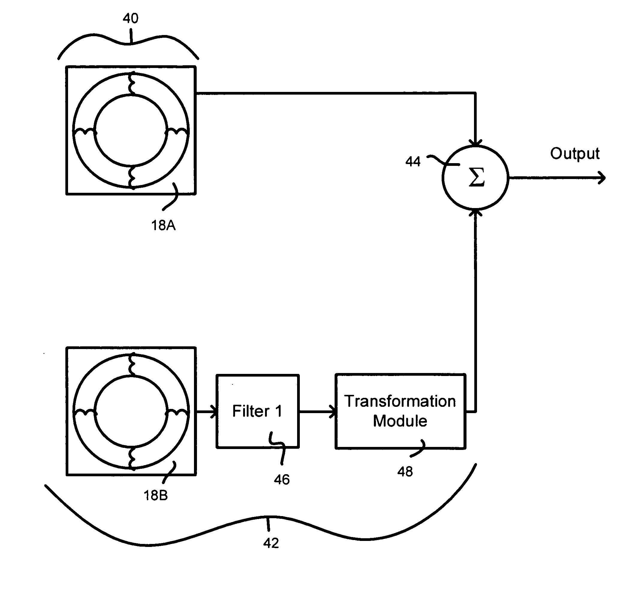
[0023] In illustrative embodiments, a microphone system has a primary microphone and a correction microphone coupled to the same base to both receive the same noise signals (e.g., mechanical shock signals) and react in a corresponding manner. To improve the quality of the output audio signal it produces, the microphone system uses noise signals detected by the correction microphone to remove significant amounts of noise from the signal produced by the primary microphone. As a result, the output audio signal should have less noise than if not processed and noise is present. Details of illustrative embodiments are discussed below.

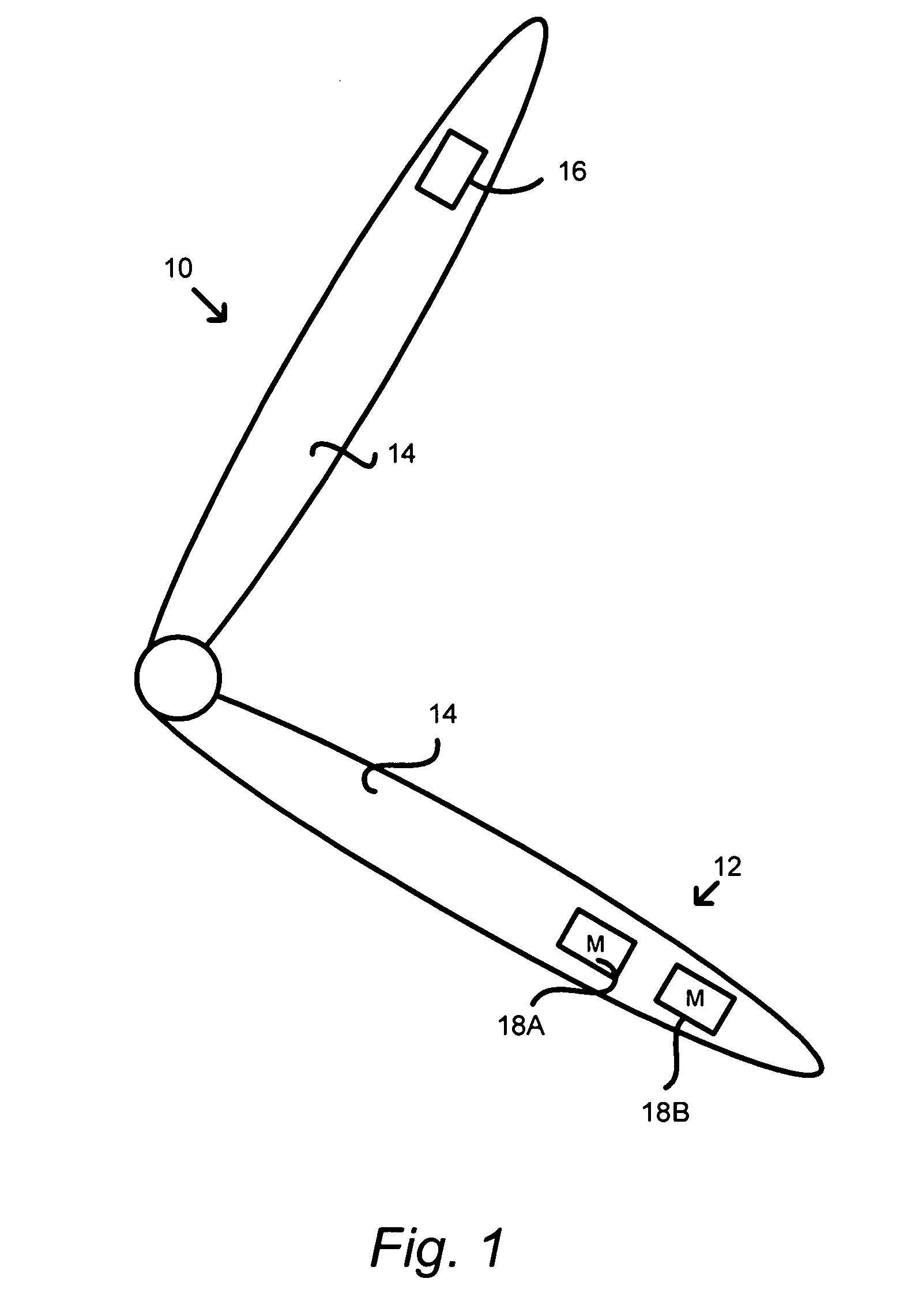
[0024]FIG. 1 schematically shows a mobile telephone acting as a base 10 for supporting a microphone system 12 configured in accordance with illustrative embodiments of the invention. To that end, the mobile telephone (also identified by reference number 10) has a plastic body 14 containing the microphone system 12 for producing an output audio signal, an ear...


PUM


Abstract

A microphone system has a base coupled with first and second microphone apparatuses. The first microphone apparatus is capable of producing a first output signal having a noise component, while the second microphone apparatus is capable of producing a second output signal. The system also has combining logic operatively coupled with the first microphone apparatus and the second microphone apparatus. The combining logic uses the second output signal to remove at least a portion of the noise component from the first output signal.

Description

PRIORITY [0001] This patent application claims priority from provisional U.S. patent application No. 60 / 710,515, filed Aug. 23, 2005, entitled, “MICROPHONE SYSTEM,” and naming Kieran Harney as the inventor, the disclosure of which is incorporated herein, in its entirety, by reference.FIELD OF THE INVENTION [0002] The invention generally relates to microphones and, more particularly, the invention relates to improving the performance of microphones. BACKGROUND OF THE INVENTION [0003] Condenser microphones typically have a diaphragm that forms a capacitor with an underlying backplate. Receipt of an audible signal causes the diaphragm to vibrate to form a variable capacitance signal representing the audible signal. It is this variable capacitance signal that can be amplified, recorded, or otherwise transmitted to another electronic device. [0004] Problems arise, however, when the microphone is subjected to a mechanical shock. Specifically, mechanical shocks can cause the diaphragm to v...

Claims


Application Information

Patent Timeline
Patent Type & Authority Applications(United States)
IPC IPC(8): H04R3/00
CPCH04M1/035H04M1/19H04R2410/05H04R1/245H04R3/005H04M1/6008
Inventor HARNEY, KIERAN P.WEIGOLD, JASONELKO, GARY
Owner INVENSENSE
Why Eureka
Try Eureka