
Video encoding device

a video encoding and video technology, applied in the field of video encoding devices, can solve the problem of the upper limit of the number of channels recordable, and achieve the effect of improving the usability of the video encoding devi

Inactive Publication Date: 2007-03-01
HITACHI LTD
View PDF5 Cites 15 Cited by
  • Summary
  • Abstract
  • Description
  • Claims
  • Application Information

AI Technical Summary

Benefits of technology

[0009] Accordingly, a GUI (Graphical User Interface) is desired in view of usability because encoding can be performed more than the number of encoders by using the limited number of encoders, a recording channel can be added, even when recording is being performed by using all the encoders, without stopping the encoding of such channels, and the above mechanism is easily understandable to the user and an operation can be made intuitively.
[0010] It is an object of the invention to improve the usability of the video encoding device.
[0012] According to this construction, for example, more channels can be encoded at the same time by using a multichannel encoder having an upper limit in the number of channels that can be originally encoded at the same time. And, another recording channel can be added without stopping a recording channel. And, it becomes possible to perform the above operation intuitively and easily by the GUI.
[0013] According to the invention, the usability of the video encoding device can be improved.

Problems solved by technology

However, according to the above method, the upper limit of the number of channels recordable at the same time depends on the number of encoders mounted, and no more larger number of channels can be recorded at the same time.

Method used


Image

  • Video encoding device
  • Video encoding device
  • Video encoding device

Examples


Embodiment Construction

[0027] An embodiment of the present invention will be described below with reference to the drawings.

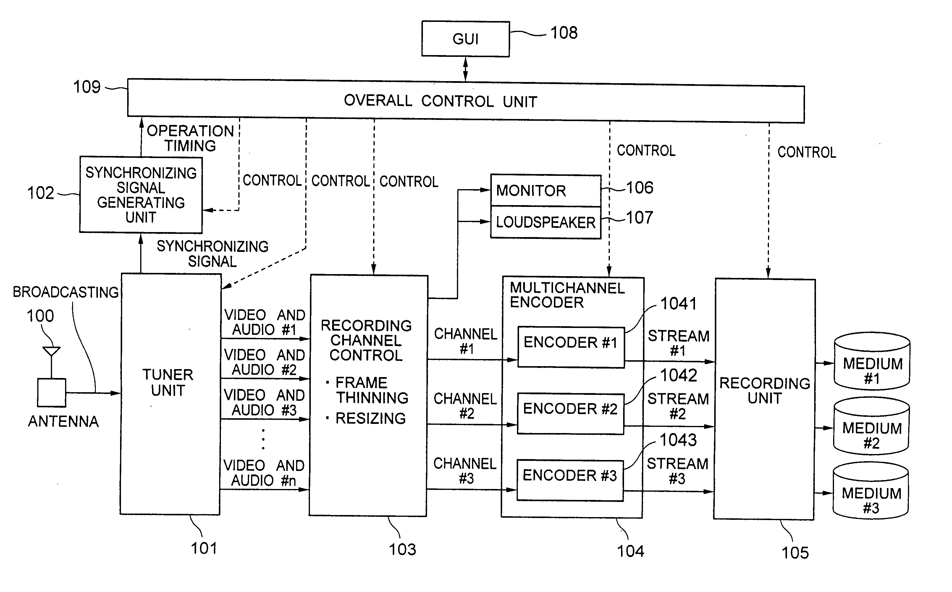
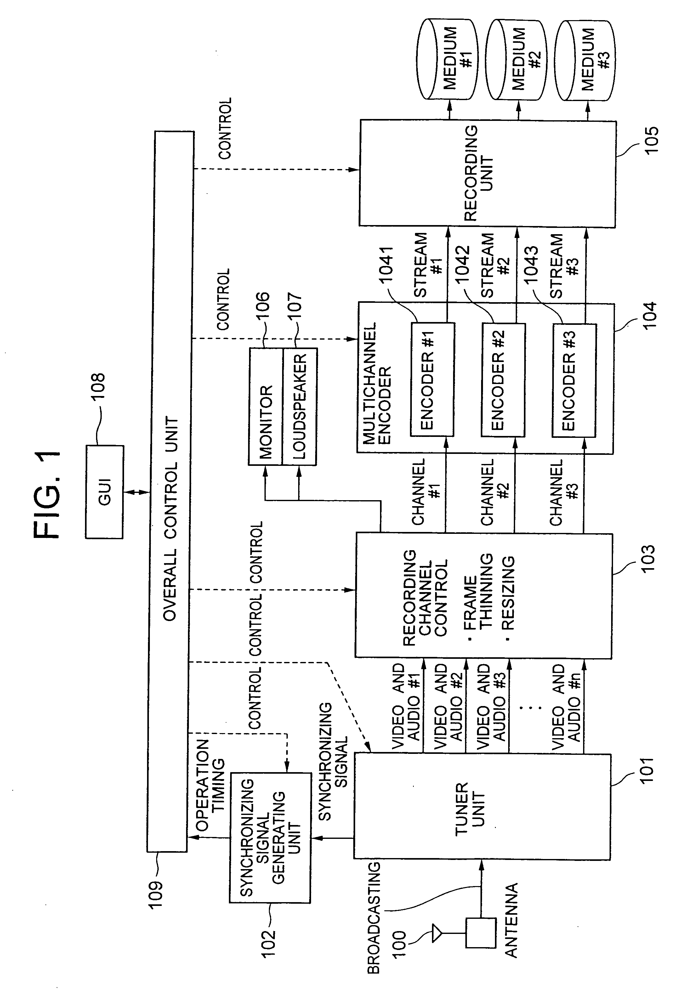
[0028]FIG. 1 shows a structure of the video encoding device (encoder) of the first embodiment of the invention.

[0029] This video encoding device is a device capable of simultaneously recording by compression encoding the selected programs of one or more channels in the received analog terrestrial broadcasting using a video encoding method such as, for example, MPEG-2 format and comprises an antenna 100, a tuner unit 101, a synchronizing signal generating unit 102, a recording channel control unit 103, a multichannel encoder 104, a recording unit 105, a monitor 106, a loudspeaker 107, a GUI 108, and an overall control unit 109.

[0030] Among them, the monitor 106 and the loudspeaker 107 are not essential but required only when a certain channel received by the tuner unit 10 is watched. The GUI 108 is also not essential but required when the overall control unit 109 is controlled inte...


PUM


Abstract

A video encoding device capable of recording a plurality of videos at the same time is provided. It is a device capable of performing simultaneous compression encoding and recording of programs of at least one or more channels selected by using, for example, a video encoding method such as an MPEG-2 format, comprises an antenna, a tuner unit, a synchronizing signal generating unit, a recording channel control unit, a multichannel encoder, a recording unit, a monitor, a loudspeaker, a GUI and an overall control unit, and controls the recording channel control unit so that the encoding processing by the multichannel encoder is decreased.

Description

BACKGROUND OF THE INVENTION [0001] The present invention relates to a video encoding device and method for compression encoding of certain video data according to a prescribed method. [0002] As a background art of this technical field, there is, for example, JP-A-2002-232884. This publication describes, “It provides an image encoding device that can perform a plurality of encoding independently under different conditions and can be realized at a low cost” as an object. As a resolution approach, it describes, “A first encoding control unit 108 and a second encoding control unit 109 each perform encoding control of images stored in a first encoding object image storage unit 100 and a second encoding object image storage unit 101 and perform encoding processing by an encoding unit 102. At this time, a time division encoding control unit 110 controls to enable to perform time division processing of encoding and realizes a plurality of encoding at the same time. To perform encoding under...

Claims


Application Information

Patent Timeline
Patent Type & Authority Applications(United States)
IPC IPC(8): H04N7/26H04N5/92H04N19/00H04N19/132H04N19/134H04N19/156H04N19/172H04N19/587H04N19/59H04N19/70
CPCH04N19/61
Inventor YOSHIDA, DAISUKEINATA, KEISUKE
Owner HITACHI LTD
Learn More