Flushing controlling mechanism

a control mechanism and flushing technology, applied in sewer systems, sewage draining, construction, etc., can solve the problems of large amount of water wasted, and achieve the effect of generating siphon effect, saving water, and reducing was

Inactive Publication Date: 2007-03-08
LIAO FU CHANG
View PDF3 Cites 9 Cited by
  • Summary
  • Abstract
  • Description
  • Claims
  • Application Information

AI Technical Summary

Benefits of technology

[0006] The primary objective of the present invention is to provide an improved flushing controlling mechanism to effectively generate siphon effect with little amount of water such that water is saved.
[0007] In yet another objective of the present invention, an auxiliary compressed air tank is provided on a side of the flushing controlling mechanism to reinforce the generation of the siphon effect so as to help such the polluted water away from the toilet bowl.
[0011] It is noted that due to the load from the weight (4) and the recoil force from the spring (21), movement of the first piston (13) downward inside the first hollow cylinder (1) is fast. As a result of the fast downward movement of the first piston (13), the vacuum effect inside the suction space (12) is generated. That is, the faster the movement of the first piston (13) is, the greater the suction force inside the suction space (12) is.
[0014] It is to be understood, however, that even though numerous characteristics and advantages of the present invention have been set forth in the foregoing description, together with details of the structure and function of the invention, the disclosure is illustrative only, and changes may be made in detail, especially in matters of shape, size, and arrangement of parts within the principles of the invention to the full extent indicated by the broad general meaning of the terms in which the appended claims are expressed.

Problems solved by technology

Therefore, in our daily life, a large amount of water is wasted just only for the generation of siphon effect to such the polluted water out of the toilet bowl.

Method used


Image

  • Flushing controlling mechanism
  • Flushing controlling mechanism
  • Flushing controlling mechanism

Examples


Embodiment Construction

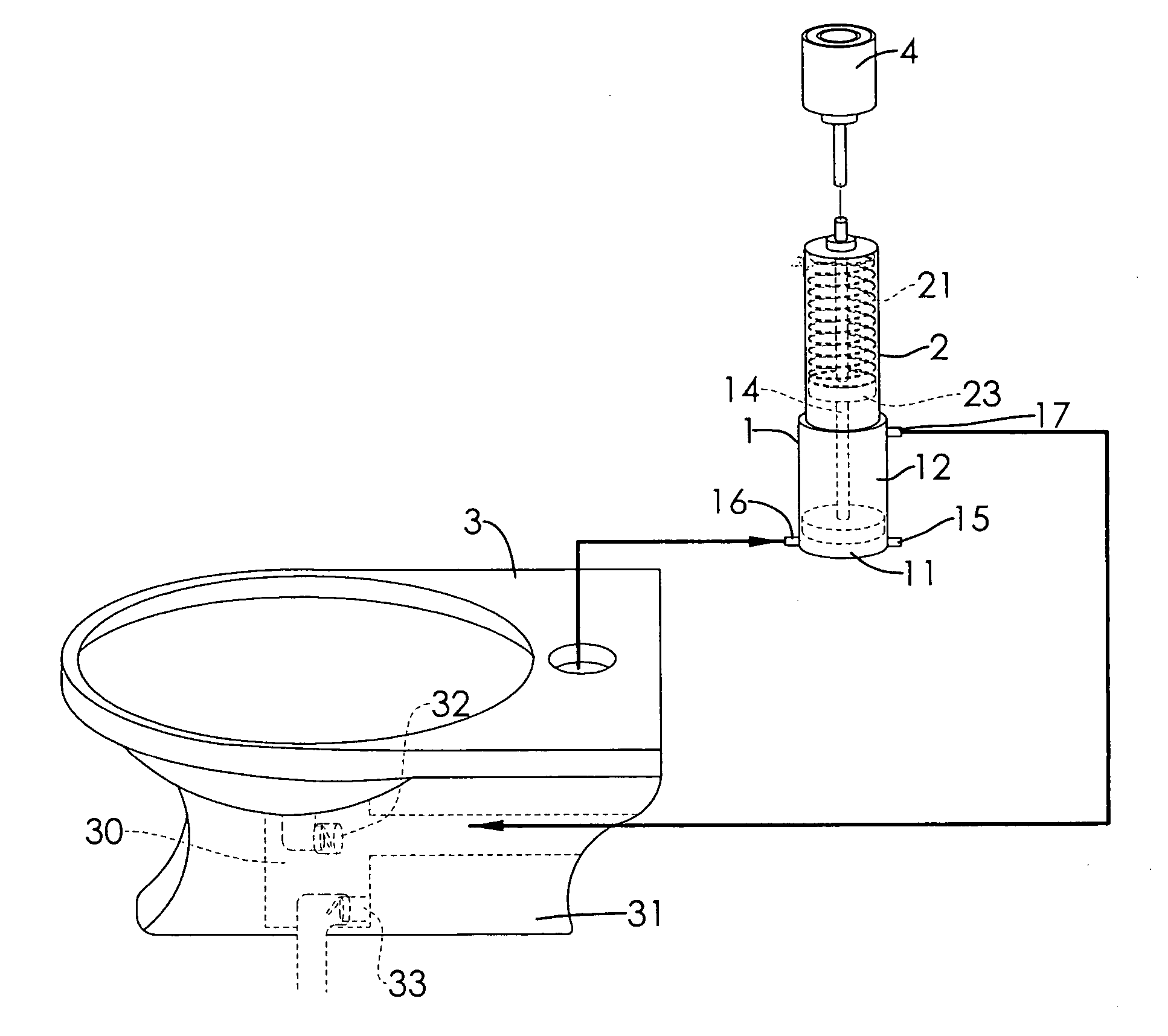
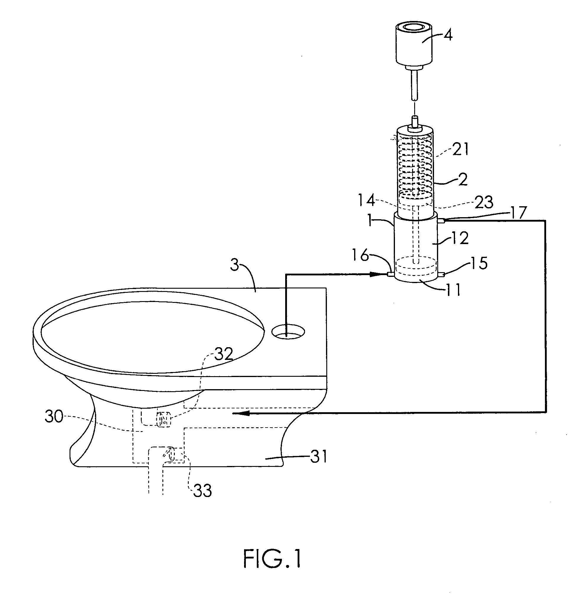
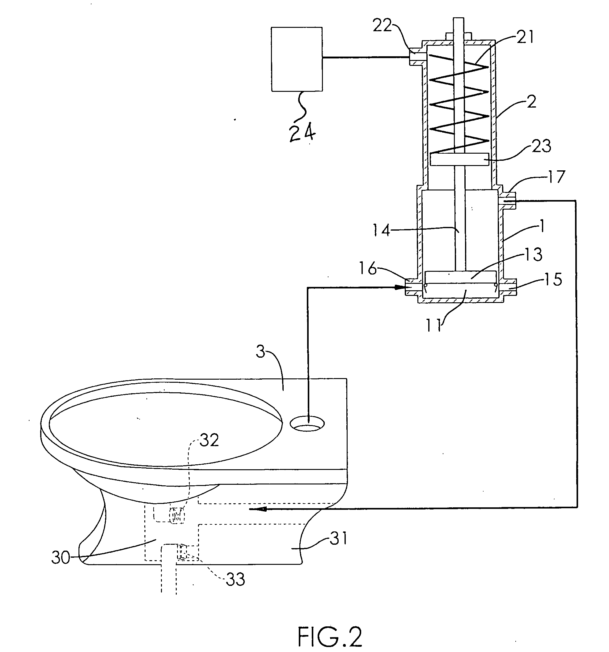
[0019] With reference to FIGS. 1, 2 and 3, it is noted that the flushing controlling mechanism in accordance with the present invention includes a first hollow cylinder (1), a second hollow cylinder (2) and a toilet bowl (3).

[0020] The first hollow cylinder (1) is provided with a water tank (11), a suction space (12), a first piston (13) movably received inside the water tank (11) and the suction space (12), a linking rod (14) extending from a side face of the first piston (13), an inlet (15) in communication with the water tank (11) and an outlet (16) in communication with both the water tank (11) and the inlet (15). It is noted that dimension of the water tank (11) as well as the suction space (12) is variant depending on position of the first piston (13). Therefore, when the first piston (13) is moving in a first direction, the dimension of the suction space (12) is increased and the dimension of the water tank (11) is decreased. On the other hand, when the first piston (13) is ...


PUM


Abstract

A flushing controlling mechanism includes a toilet bowl having a trap, a room selectively communicating with the trap via a first waste pipe and a second waste pipe alternately communicating with the room, a hollow cylinder received in the toilet bowl, a first piston movably inside the hollow cylinder, an inlet adapted to be connected to a water source to allow water to flow into the water tank so as to move the first piston upward inside the hollow cylinder, an outlet selectively communicating with the trap of the toilet bowl and a first opening communicating with the suction space and the room of the toilet bowl and a device to accelerate downward movement of the first piston such that the waste in the trap of the toilet bowl is sucked to the room and disposed from the second waste pipe.

Description

BACKGROUND OF THE INVENTION [0001] 1. Field of the Invention [0002] The present invention relates to a flushing controlling mechanism, and more particularly to a flushing controlling mechanism to save water used in generation of a siphon effect. [0003] 2. Description of the Prior Art [0004] When flushing a toilet, large volume of water stored in a water tank is suddenly released to a drainage pipe to generate siphon effect such that the polluted water in the toilet bowl is sucked into the drainage pipe. The suction of the polluted water is based on the siphon effect and the generation of the siphon effect is dependent from the sudden release of large volume of water in the water tank. Therefore, in our daily life, a large amount of water is wasted just only for the generation of siphon effect to such the polluted water out of the toilet bowl. [0005] To overcome the shortcomings, the present invention tends to provide an improved flushing controlling mechanism to mitigate the aforeme...

Claims


Application Information

Patent Timeline
Patent Type & Authority Applications(United States)
IPC IPC(8): E03D11/00
CPCE03F1/006E03D3/10
Inventor LIAO, FU-CHANG
Owner LIAO FU CHANG
Why Eureka
Try Eureka