Apparatus for providing high quality power

a high-quality, power-generation technology, applied in emergency power supply arrangements, electric generator control, instruments, etc., can solve the problems of safety risks, bulkiness and expense of distributing ac power, and inability to meet the needs of ac power supply, so as to reduce the number of wires and the current needed, reduce the inefficiency of smps, and reduce the effect of wiring circular mills

Inactive Publication Date: 2007-03-08
VALIDUS DC SYSTEMS
View PDF35 Cites 17 Cited by
  • Summary
  • Abstract
  • Description
  • Claims
  • Application Information

AI Technical Summary

Benefits of technology

[0011] It is another object of the present disclosure to utilize one AC utility and emergency power source, preferably a generator, as the incoming main and emergency feeds to make the system reliable in case of a utility power outage.
[0012] In one embodiment, the system cycles through a transfer switch with overlap transition to utility, optional. The transfer switch will take one emergency and one utility and will switch between the two when either manually initiated or loss of utility power has occurred. The generator will feed a distribution panel sized to power a bridge diode rectifier, house loads and air conditioning, utilizing 480 / 3 / 60 input and 300-600 VDC output. The rectifier will be designed to reduce DC ripple. In another embodiment, the system will utilize a flywheel battery-less DC power supply source, in parallel to the output of a main rectifier, to generate 300-600 VDC and tie into the output of the rectifier. The system utilizes DC output power from the rectifier to charge the flywheel. When AC power is lost to the main rectifier input, the flywheel will discharge the kinetic storage into the load side of the rectifier until such time that the emergency generator has started and has taken over the critical load. When the emergency source is on line it will supply power to both the load and will also recharge the flywheel device to 100% preparing the system for the eventual return to utility. Upon the return or stabilization of utility power consistently for a set period, the transfer switch will retransfer the system load to the utility. During this transfer, the break in the system power will once again be bridged by the flywheel source in the opposite direction.
[0013] Preferably, the 300-600 VDC from the output of the main rectifier will distribute throughout the facility reducing both the wire size and the current necessary to run a Power Converter Unit or PCU that will step the high voltage down to useable 23-48 VDC to power plants or computers that are designed to utilize 23-48 volts DC. Thereby allowing the computers to be supplied without a customary switch mode power supply therefore reducing the inefficiencies of the SMPS saving energy of up to 30% and reducing wiring circular mill, reducing cooling requirements, rid the plant of chemical storage batteries and reduce its equipment infrastructure required spacing and significantly increasing the power reliability. This attribute will allow more of the critical indoor square footage to be utilized for the electronics necessary to increase business.
[0014] In another embodiment, at certain determined interval areas, dependant upon loading and distance, a specially designed DC-to-DC converter, or Power Converter Unit (“PCU”), utilizing intergate bi-polar transistor (hereinafter “IGBT”) technology, redundant power supplies or 30 kW drawers and a 5-20 kHz DC controller that both senses and fires an IGBT will be placed. The PCU can be fed by up to two totally independent power systems providing highly reliable outage protection. Additionally, the PCU is highly resistant to faults and once again adding to the high quality power output. The IGBT will efficiently convert line side DC high voltage to secondary low side voltage remaining efficient and tightly controlled throughout the potential voltage drop on the primary side down to 300 VDC. This PCU is much like a DC to DC transformer. From the output of the IGBT device, voltage and current will be distributed to local or close devices that utilize 48 volts DC without the issues of voltage drop and excessive heat produced by the SMPS. This voltage can be controlled by remotely placing a sensor at the furthest device from the converter.
[0015] Another highly important concept to this power quality system is the utilization of a sophisticated cooling system to rid the space of the heat produced by the efficient delivery of power by the PCU to the telecommunications and data processing loads. The PCU will deliver power to racks where the technology will reside. Virtually all of the delivered power will be utilized by electronic loads. These loads will turn this power completely into heat. Technology today is attempting to compact as many devices in as small a space as possible. In order to provide for this condition, a Power Cooling rack (PCR) will be provided that can liquid cool a plate fin heat exchanger located in the bottom of the rack as well as variable speed fans that will efficiently meter air and will cool the computers in the rack up to 20 kW. The best device being utilized today can rid the space of up to 5-7 kW. These racks will provide for dual fed 48 volt DC distribution for protection against power outage of one of the sources increasing reliability.

Problems solved by technology

Despite this proliferation of the use of AC power, various problems are well-known.
Despite these improvements, many drawbacks to the AC power still have not been overcome.
Many AC power systems require battery backup and second 100% rated redundant feeds and are still inefficient at supplying the necessary power and redundancy.
Further, the safety risk, bulkiness and expense of distributing AC power is well documented.
However, the prior ability to produce DC power and scale distribution thereof has been a hurdle yet to be overcome.
Batteries in such applications have many limitations.
When the batteries age, capacity reduces to the point of requiring replacement that creates a disposal problem.
Further, the ability to produce and draw large amounts of power from a DC battery system is dependant upon the amount and size of the batteries and require large distribution systems as DC distribution systems are oversized for DC voltage drop.
Moreover, switching between sources is a recognized problem and often incurs momentary lapses in provision of the power needed.
In the past no technology has been available to economically produce and distribute highly reliable high capacity DC power for use in both centers.
However, as a result of not being able to scale DC power much like an AC transformer for distribution, technology dependent upon ready access to DC power has stagnated.
Moreover, prior art systems have required large amounts of wiring and conditioning equipment for electrically interconnecting the AC voltage source with the load.
Typically, the electrical interconections are quite bulky and require a large amount of copper.
Theses AC driven SMPS generate heat and draw significant power and are very inefficient.
As a result of the high heat generation and a limited amount of cooling capacity, data processing equipment must be spread out to facilitate proper cooling, therefore data centers have less space for processing equipment and an overall decreased cooling load efficiency.

Method used


Image

  • Apparatus for providing high quality power
  • Apparatus for providing high quality power
  • Apparatus for providing high quality power

Examples


Embodiment Construction

[0025] The present invention overcomes many of the prior art problems associated with power supplies. The advantages, and other features of the system disclosed herein, will become more readily apparent to those having ordinary skill in the art from the following detailed description of certain preferred embodiments taken in conjunction with the drawings which set forth representative embodiments of the present invention and wherein like reference numerals identify similar structural elements.

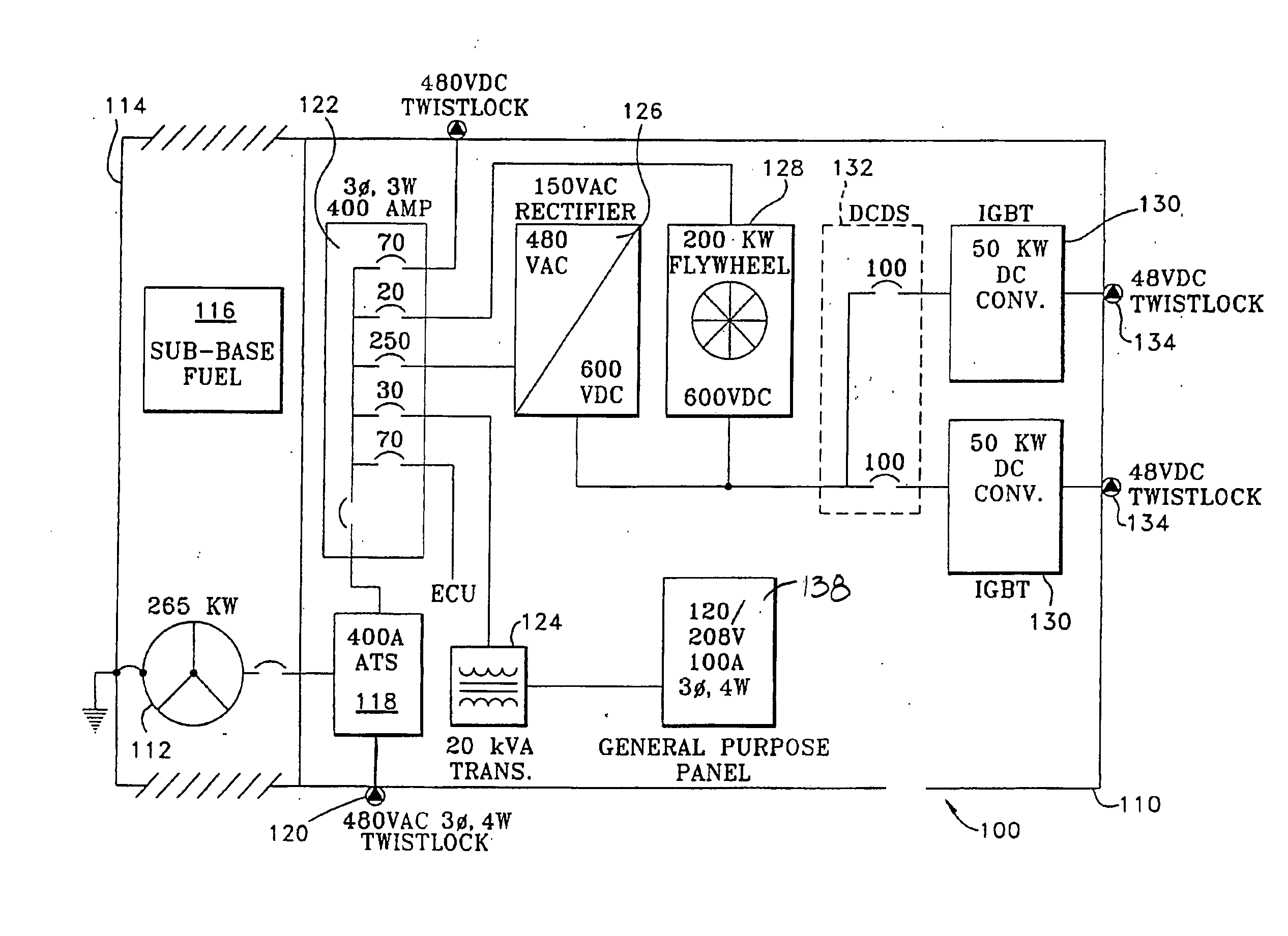
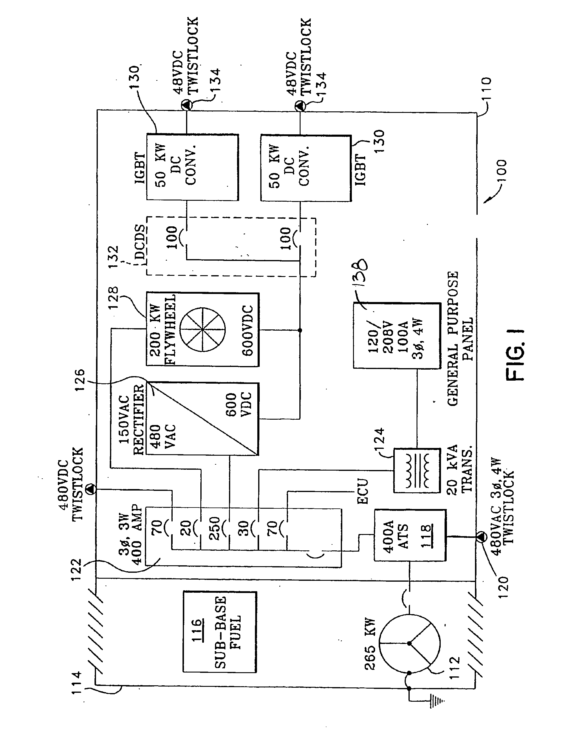
[0026] Referring to FIG. 1, an enclosure 110 is utilized to protect the system 100 from the elements as well as provide the proper internal environment necessary for the component pieces to function properly. This environment is preferably 40-104 degrees F., non-condensing. In a preferred embodiment, the enclosure 110 is an ECOBAY™ enclosure available from Sanmina-SCI Corp. of 2700 North First Street, San Jose, Calif. 95134. The system 100 is designed to be stationary or fixed. The enclosure 1...


PUM


Abstract

There is provided a system that includes (a) a power feed that distributes a high DC voltage in a building, where the high DC voltage is in a range of about 300 to 600 VDC, (b) a converter, coupled to the power feed, that receives the high DC voltage, and scales the high DC voltage to a low DC voltage, and (c) a controller that controls a firing rate of the converter so that the low DC voltage is in a range of about 23 to 48 VDC.

Description

CROSS-REFERENCE TO RELATED APPLICATION [0001] The present application is a continuation of U.S. patent application Ser. No. 10 / 700,076, filed Nov. 3, 2003, which claims priority to U.S. Provisional Patent Application No. 60 / 423,127 filed Nov. 1, 2002 and U.S. Provisional Patent Application No. 60 / 453,235 filed Mar. 10, 2003. The content of each of the above-noted applications is herein incorporated by reference in its entirety.BACKGROUND OF THE INVENTION [0002] 1. Field of the Invention [0003] The subject disclosure relates to systems for providing high quality power, and cooling and more particularly to an improved system for providing uninterrupted DC power for the telephone communications, data processing and industrial equipment. [0004] 2. Background of the Related Art [0005] Traditionally, AC commercial power has been used as the primary power source for a wide variety of applications such as computers, data processing equipment, telephony circuitry and other solid state techno...

Claims


Application Information

Patent Timeline
Patent Type & Authority Applications(United States)
IPC IPC(8): H02J7/00G05D11/00H02J1/00H02J9/06H02J9/08H02K7/02H02P9/04
CPCH02J9/08H02J9/066H02P9/04
Inventor KRAUS, RUDY
Owner VALIDUS DC SYSTEMS
Why Eureka
Try Eureka