[0011]It is another object of the present disclosure to utilize one AC utility and emergency power source, preferably a generator, as the incoming main and emergency feeds to make the system reliable in case of a utility power outage.
[0012]In one embodiment, the system cycles through a
transfer switch with overlap transition to utility, optional. The
transfer switch will take one emergency and one utility and will switch between the two when either manually initiated or loss of utility power has occurred. The generator will feed a distribution panel sized to power a bridge
diode rectifier, house loads and
air conditioning, utilizing 480 / 3 / 60 input and 300–600 VDC output. The
rectifier will be designed to reduce DC
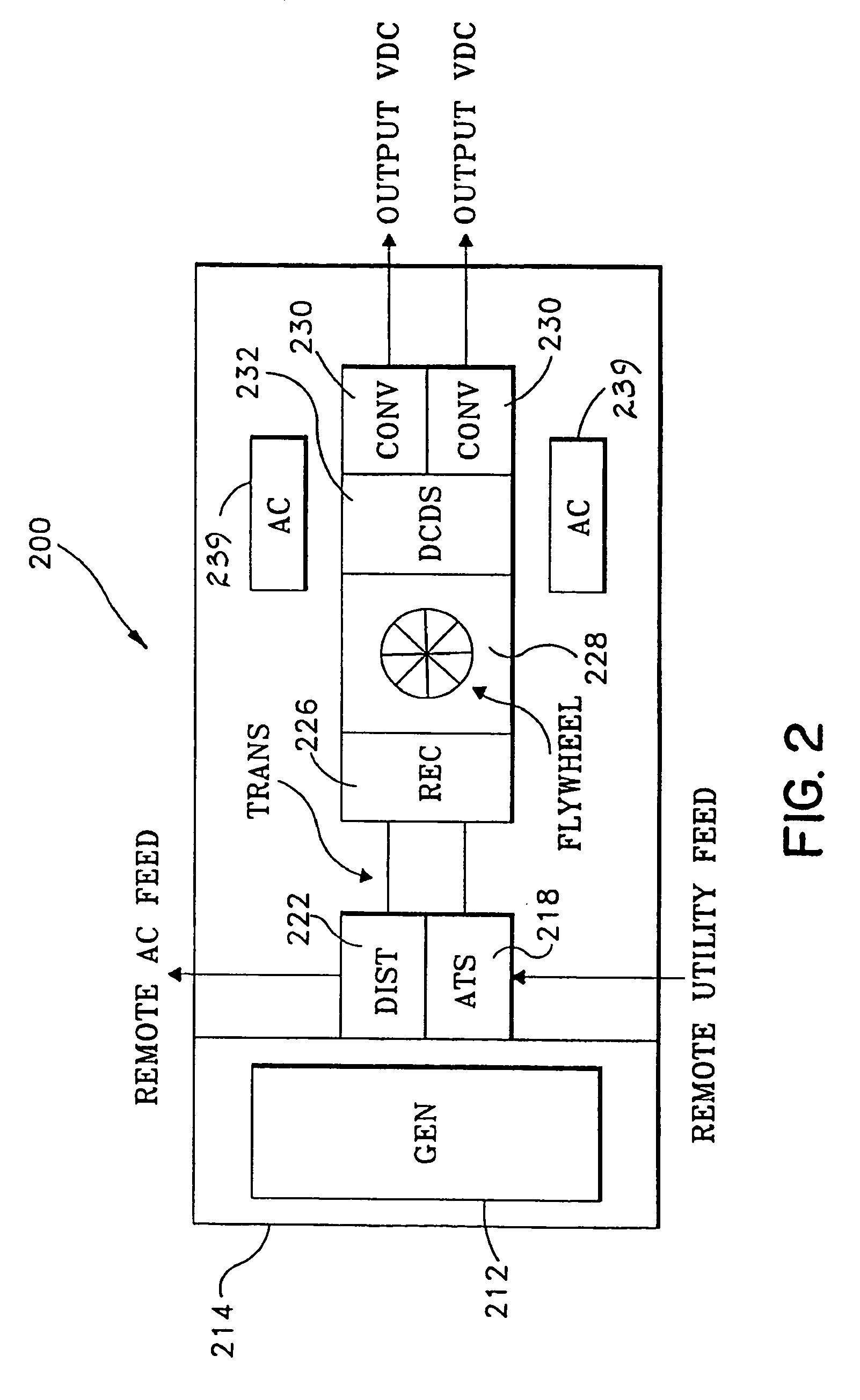
ripple. In another embodiment, the system will utilize a
flywheel battery-less DC power supply source, in parallel to the output of a main
rectifier, to generate 300–600 VDC and tie into the output of the rectifier. The system utilizes DC output power from the rectifier to charge the
flywheel. When AC power is lost to the main rectifier input, the
flywheel will
discharge the kinetic storage into the load side of the rectifier until such time that the emergency generator has started and has taken over the
critical load. When the emergency source is on line it will supply power to both the load and will also recharge the flywheel device to 100% preparing the system for the eventual return to utility. Upon the return or stabilization of utility power consistently for a set period, the
transfer switch will retransfer the system load to the utility. During this transfer, the break in the system power will once again be bridged by the flywheel source in the opposite direction.
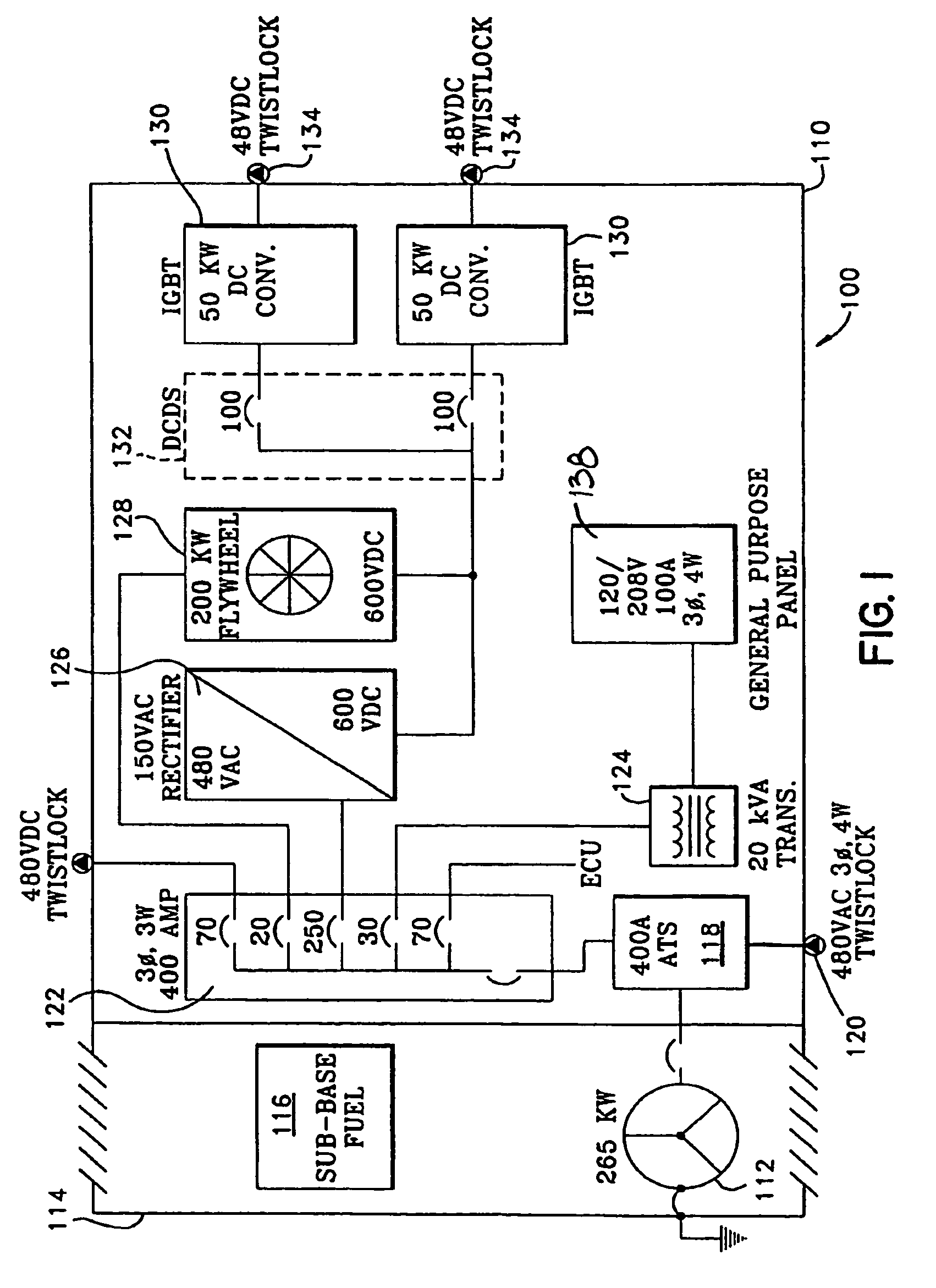
[0013]Preferably, the 300–600 VDC from the output of the main rectifier will distribute throughout the facility reducing both the wire size and the current necessary to run a Power Converter Unit or PCU that will step the
high voltage down to useable 23–48 VDC to power plants or computers that are designed to utilize 23–48 volts DC. Thereby allowing the computers to be supplied without a customary switch mode power supply therefore reducing the inefficiencies of the SMPS saving energy of up to 30% and reducing wiring circular mill, reducing cooling requirements, rid the
plant of
chemical storage batteries and reduce its equipment infrastructure required spacing and significantly increasing the
power reliability. This attribute will allow more of the critical indoor square footage to be utilized for the
electronics necessary to increase business.
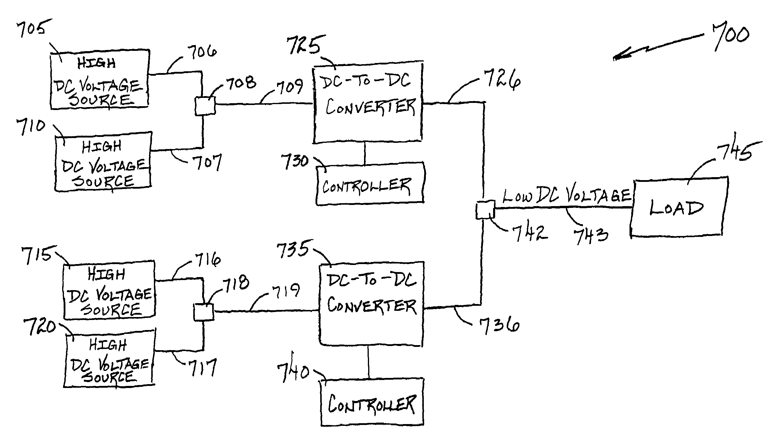
[0014]In another embodiment, at certain determined interval areas, dependant upon loading and distance, a specially designed DC-to-
DC converter, or Power Converter Unit (“PCU”), utilizing intergate bi-polar
transistor (hereinafter “IGBT”) technology, redundant power supplies or 30 kW drawers and a 5–20 kHz DC controller that both senses and fires an IGBT will be placed. The PCU can be fed by up to two totally independent power systems providing highly reliable outage protection. Additionally, the PCU is highly resistant to faults and once again adding to the high quality
power output. The IGBT will efficiently convert line side DC
high voltage to secondary low side
voltage remaining efficient and tightly controlled throughout the potential
voltage drop on the primary side down to 300 VDC. This PCU is much like a DC to DC
transformer. From the output of the IGBT device, voltage and current will be distributed to local or close devices that utilize 48 volts DC without the issues of
voltage drop and excessive heat produced by the SMPS. This voltage can be controlled by remotely placing a sensor at the furthest device from the converter.
[0015]Another highly important concept to this
power quality system is the utilization of a sophisticated cooling system to rid the space of the heat produced by the efficient delivery of power by the PCU to the telecomunications and data
processing loads. The PCU will deliver power to racks where the technology will reside. Virtually all of the delivered power will be utilized by electronic loads. These loads will turn this power completely into heat. Technology today is attempting to compact as many devices in as small a space as possible. In order to provide for this condition, a Power Cooling rack (PCR) will be provided that can liquid cool a
plate fin heat exchanger located in the bottom of the rack as well as variable speed fans that will efficiently meter air and will cool the computers in the rack up to 20 kW. The best device being utilized today can rid the space of up to 5–7 kW. These racks will provide for dual fed 48
volt DC distribution for protection against power outage of one of the sources increasing reliability.

