System for regulating the output of a high-voltage, high-power, DC supply

Active Publication Date: 2014-07-24
DIVERSIFIED TECH INC
View PDF5 Cites 1 Cited by
  • Summary
  • Abstract
  • Description
  • Claims
  • Application Information

AI Technical Summary

Benefits of technology

The patent describes a system that helps regulate the output of a high-voltage, high-power DC supply. This system includes a high-voltage DC power supply, a storage capacitor, and at least one non-dissipative regulator. The regulator has a lower output voltage range than the high-voltage DC power supply and includes an internal storage and a control circuit to maintain a high-voltage output on the load to reduce ripple. The technical effect of this system is to provide a more stable and efficient DC power output.

Problems solved by technology

Since there is very little dissipation in superconducting cavities, the pulses for these are much longer, typically of order a few milliseconds, because this reduces the peak power required.
These factors present a number of challenges.
One challenge associated with long, e.g., millisecond scale, pulses at high current is that they couple substantial charge, which decreases the voltage on the capacitors in the modulator.
While it is conceptually possible to increase the capacitance to limit this droop, the size of a capacitor needed to achieve this is typically too large to be practical.
Another problem associated with pulsed modulators is that they do not draw constant power.
Flicker can be highly disruptive to both local power users and the grid itself.
One of the significant challenges to these designs is the need to regulate voltage droop in a long-pulse modulator.
However, the power dissipated in a vacuum tube would be substantial.
One problem with this implementation is the bridge circuit switches full power repeatedly during a pulse.
Such a design requires large switching transistors.
However, this adds significant complexity to the device.
Developing the modulator system for the SNS has taken ten years and has had multiple failures in the switching transistors, the resonant capacitors across the IGBTs, and the high-voltage transformers.
Moreover, the droop regulation is not yet functional.
A high-power main switching supply is significantly more expensive than an SCR-controlled supply, which cannot be used in this architecture.
One problem with the conventional pulse-step modulator is that the boost regulators need to be large enough to carry all the power.
This is much more expensive than an SCR-controlled power supply.
Additional Marx stages can be switched on during the pulse to compensate for droop, which add to the overall cost and complexity of the modulator.
Such a design also requires an expensive switching power supply to eliminate flicker.
While a switching supply would produce much less ripple, it would be more expensive.
Although this method is somewhat effective, it may be necessary in some instances to reduce the ripple even further.

Method used


Image

  • System for regulating the output of a high-voltage, high-power, DC supply
  • System for regulating the output of a high-voltage, high-power, DC supply
  • System for regulating the output of a high-voltage, high-power, DC supply

Examples


Embodiment Construction

[0045]Aside from the preferred embodiment or embodiments disclosed below, this invention is capable of other embodiments and of being practiced or being carried out in various ways. Thus, it is to be understood that the invention is not limited in its application to the details of construction and the arrangements of components set forth in the following description or illustrated in the drawings. If only one embodiment is described herein, the claims hereof are not to be limited to that embodiment. Moreover, the claims hereof are not to be read restrictively unless there is clear and convincing evidence manifesting a certain exclusion, restriction, or disclaimer.

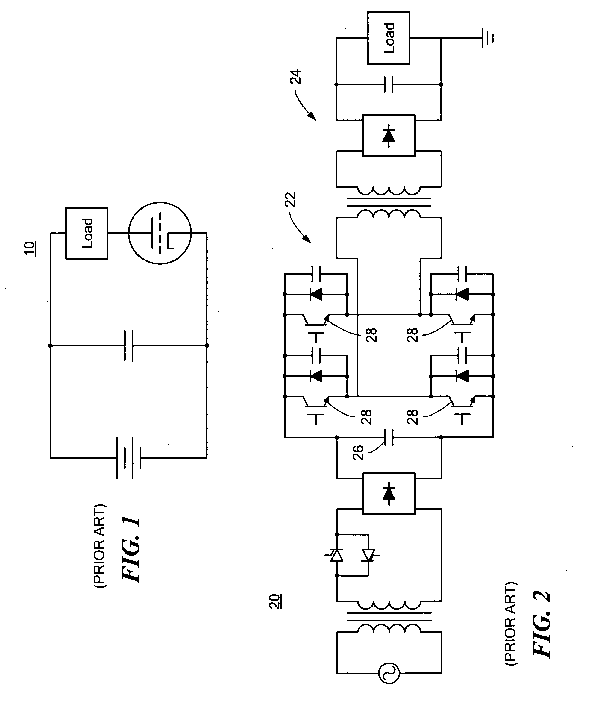
[0046]As discussed in the Background section above, there are several conventional systems used to regulate droop in long-pulsed modulators. Historically, this has been done by dissipating power with a vacuum tube 10 as shown in FIG. 1. However, the power dissipated in the vacuum tube is substantial. A system with a 10% dro...


PUM


Abstract

A system for regulating the output of a high-voltage, high-power DC supply, the system includes a high-voltage DC power supply, a storage capacitor, and at least one non-dissipative regulator having an output voltage range less than an output voltage range of the high-voltage DC power supply. The regulator includes an internal storage capacitance and a control circuit configured to maintain a desired high-voltage output on a load.

Description

FIELD OF THE INVENTION[0001]This invention relates to a system for regulating the output of a high-voltage, high-power, DC power supply.BACKGROUND OF THE INVENTION[0002]Conventional modulators used in pulsed accelerators produce electrical pulses that drive radio frequency (RF) tubes. The RF output from these tubes produces an electric field in acceleration cavities and the electric field accelerates the charged particles. The acceleration cavities can either be normally-conducting or superconducting. The pulses in normally-conducting cavities are typically only a few microseconds long to minimize the resistive dissipation in the cavities. Since there is very little dissipation in superconducting cavities, the pulses for these are much longer, typically of order a few milliseconds, because this reduces the peak power required.[0003]One example of a current long-pulse modulator is at the Spallation Neutron Source (SNS) at Oak Ridge National Laboratory. The specification for this modu...

Claims


Application Information

Patent Timeline
IPC IPC(8): G05F1/46
CPCG05F1/46H02M3/156H02M7/217
Inventor GAUDREAU, MARCEL PIERRE JOSEPHROTH, IAN SAULKEMPKES, MICHAEL ALANBUTLER, NEAL R.
Owner DIVERSIFIED TECH INC
Why Eureka
Try Eureka