
Travelling field machine

a technology of traveling field and machine body, which is applied in the direction of dynamo-electric machines, electrical apparatus, magnetic circuits, etc., can solve the problems of poor space utilization in the grooves and winding overhangs, the inability of round cross-section wires and the inability to fully utilize the cross-sectional area of the grooves

Inactive Publication Date: 2007-03-08
COMPACT DYNAMICS
View PDF9 Cites 15 Cited by
  • Summary
  • Abstract
  • Description
  • Claims
  • Application Information

AI Technical Summary

Benefits of technology

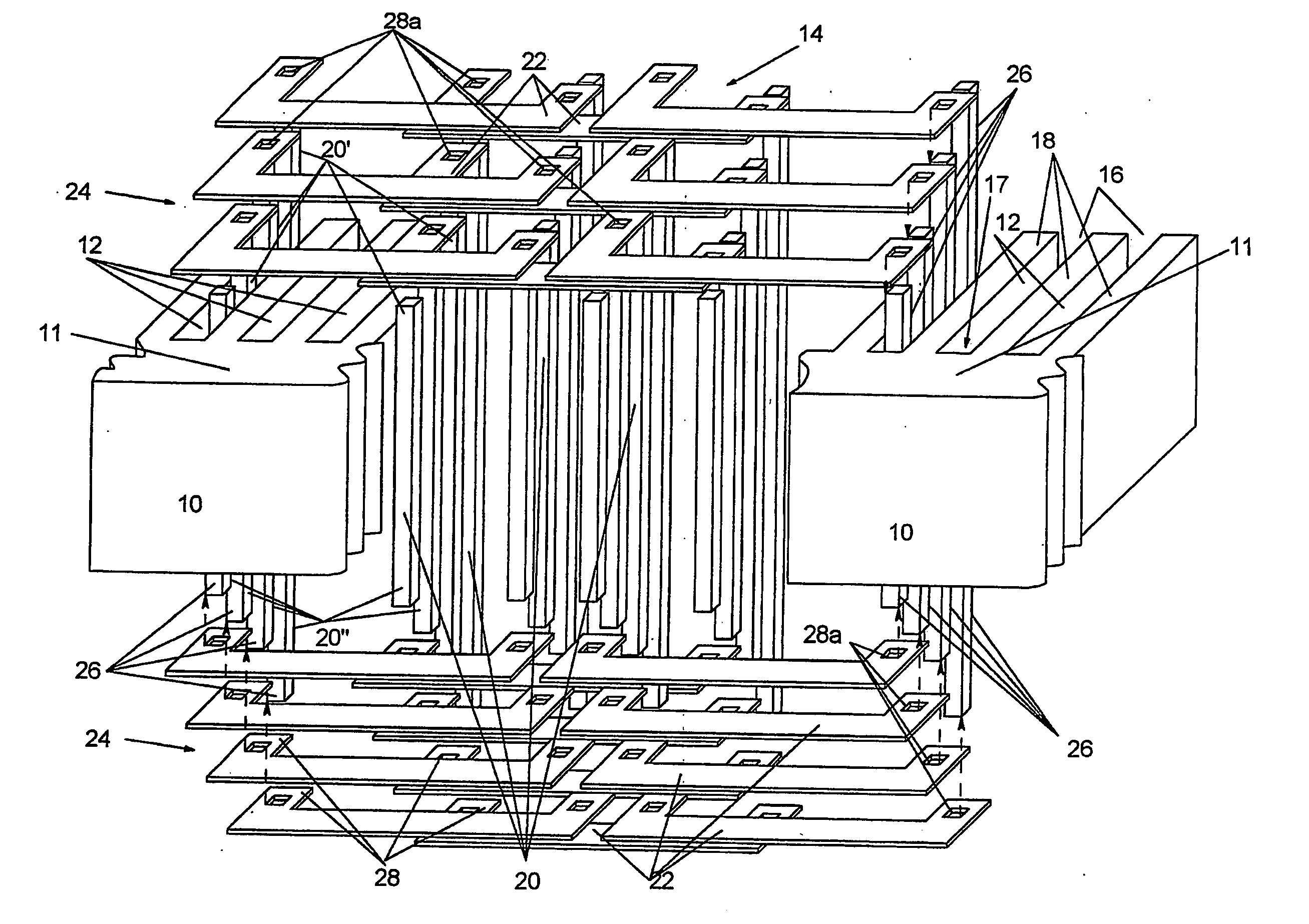
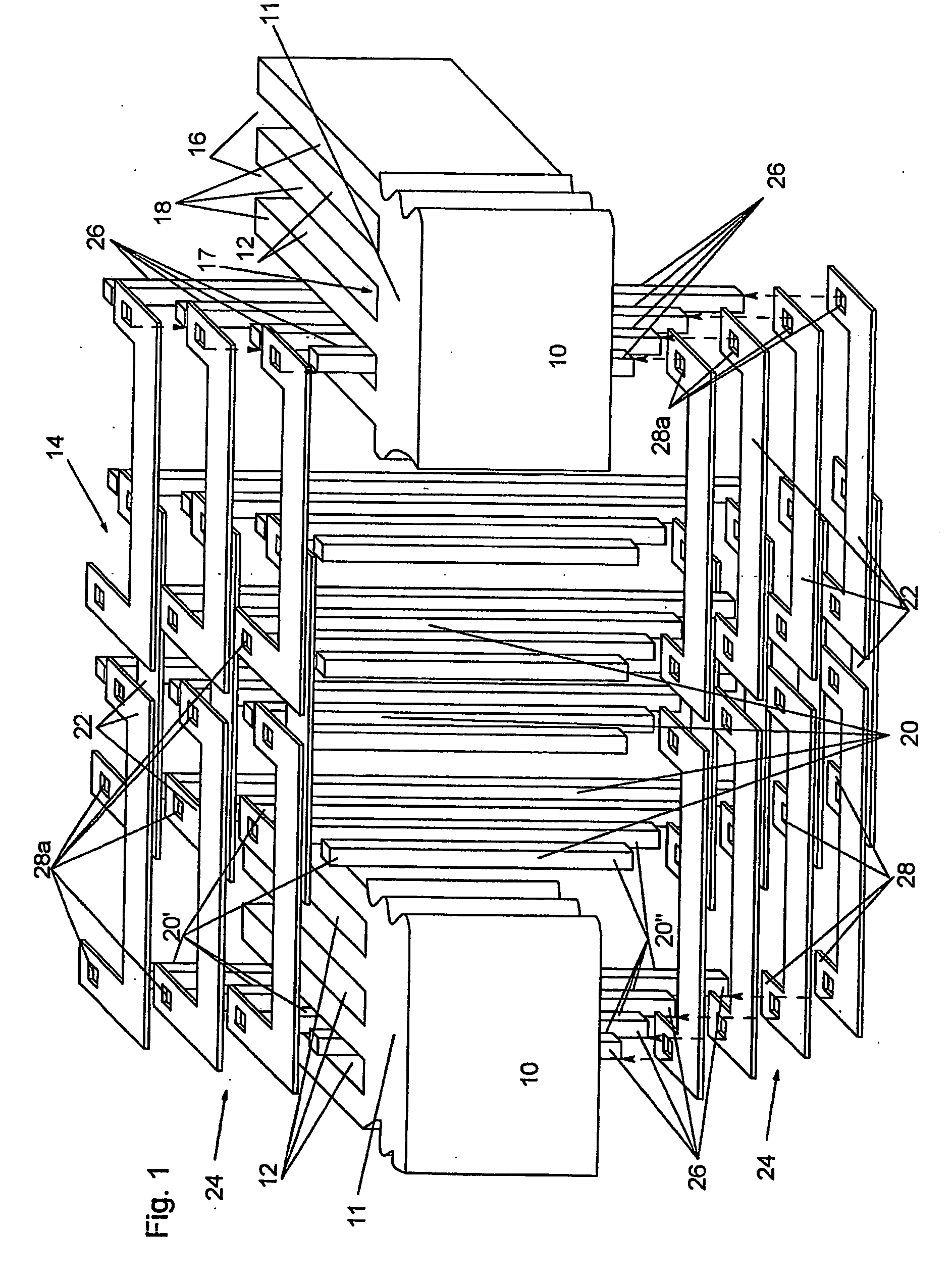
[0016] Depending on whether the electrical machine is an internal rotor or an external rotor machine, the grooves may taper or expand towards the air gap between the stator and the rotor. This allows the conductor bars arranged in the grooves, depending on their position in the groove, to have a width which is at least partially adapted to the groove width. This provides for the maximum utilisation of the available groove space.
[0017] A good space utilisation may also be achieved in that at least on one of the two faces of the stator the end connectors are not only arranged in the direction of the stator back, but also in the direction of the air gap between the stator and the rotor. In this case, the length of the conductor bars is increasing both from the stator back and the air gap between stator and rotor towards the centre of the winding chamber.

Problems solved by technology

Though a thin flexible wire may easily be placed into the grooves, it has the disadvantage of a poor space utilisation in the grooves and winding overhangs.
Wires with round cross-section cannot fully utilise the cross-sectional area of the groove.
The space in the winding overhangs is thus also utilised only inadequately, and the magnetically ineffective conductor length, the overall weight, the required space, and the ohmic losses increase.

Method used


Image

  • Travelling field machine
  • Travelling field machine
  • Travelling field machine

Examples


Embodiment Construction

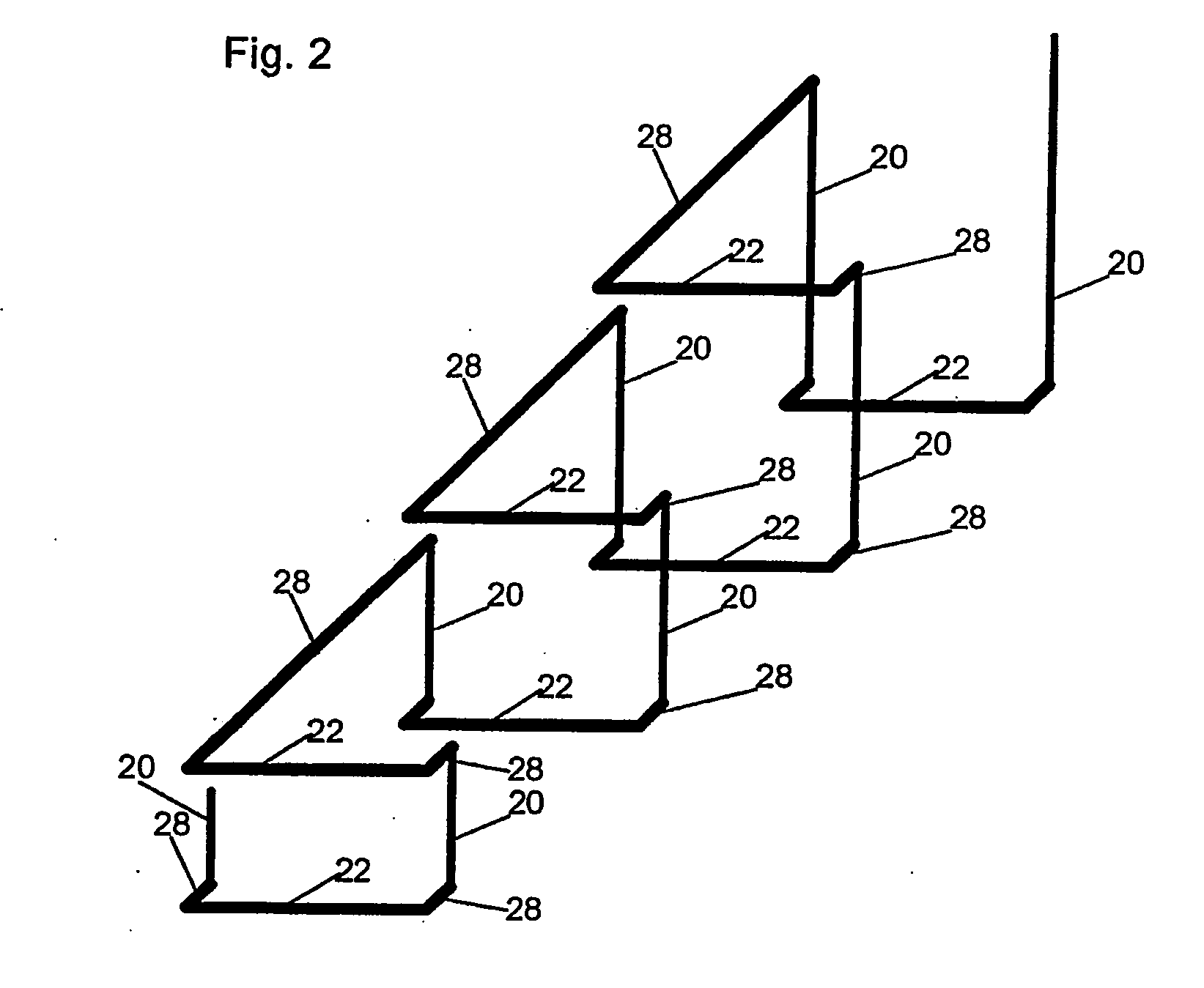
[0012] Preferably, the end connectors are provided with transverse portions at their two end areas, through which they are connected with the ends of the conductor bars. The length of the transverse portions determine how far the winding overhangs originating from the conductor bars extend across the back of the rotor or the stator.

[0013] The conductor bars may have a connecting area each at their ends, which matches with corresponding portions at the end connectors for a mechanical and electrical connection. The design of the mechanical and electrical connection may be of various kinds. The connecting areas at the ends of the conductor bars or the transverse portions of the end connectors, respectively, are formed, for example, by recesses or tapers in which or to which, respectively, the corresponding portions of the end connectors or the conductor bars, respectively, are joined and contacted by laser welding or electro-impulse welding.

[0014] The joint between the end portion of...


PUM

PropertyMeasurementUnit
Lengthaaaaaaaaaa
Shapeaaaaaaaaaa
Widthaaaaaaaaaa

Abstract

A travelling field machine with a stator and a rotor which are separated by an air gap and each of which comprises at least one stator coil or one rotor coil, with the stator or the rotor, respectively, comprising a soft magnetic iron body with a stator or rotor back, in which spaced grooves are formed, generating teeth, and in each of the grooves several conductor bars of the stator coil or the rotor coil, respectively, are arranged in series comprising end connectors arranged at the faces of the stator or the rotor, respectively, which connect the conductor bars extending across at least one groove, with the conductor bars comprising conductor portions of different length projecting beyond the faces of the stator or rotor, respectively, and the end connectors being arranged in a stacked fashion in the axial direction at the faces of the stator or the rotor.

Description

FIELD OF THE INVENTION [0001] The present invention relates to a travelling field machine. In particular, the invention relates to a travelling field machine with a stator and a rotor, each of which comprising at least one stator coil or one rotor coil, respectively, with the stator or the rotor, respectively, comprising a soft magnetic iron body with a stator or rotor back, respectively, at which spaced grooves are formed under the forming of teeth. DEFINITION OF TERMS [0002] The term “travelling field machines”, i. e. asynchronous, synchronous, reluctance machines, permanently excited electrical machines, etc. covers motors as well as generators, whereby it is of no significance in particular for the invention whether such a machine is designed as a rotating machine or, for example, as a linear motor. Moreover, the invention may be applied both to internal rotor machines and external rotor machines. BACKGROUND OF THE INVENTION [0003] In the reduction of the volume of highly effici...

Claims


Application Information

Patent Timeline
IPC IPC(8): H02K1/00H02K23/26H02K21/00H02K3/12
CPCY10T29/49009H02K3/12
Inventor GRUNDL, ANDREASHOFFMANN, BERNHARD
Owner COMPACT DYNAMICS
Learn More