
Image pickup apparatus and display control method

Active Publication Date: 2007-03-08
SONY CORP
View PDF3 Cites 50 Cited by
  • Summary
  • Abstract
  • Description
  • Claims
  • Application Information

AI Technical Summary

Benefits of technology

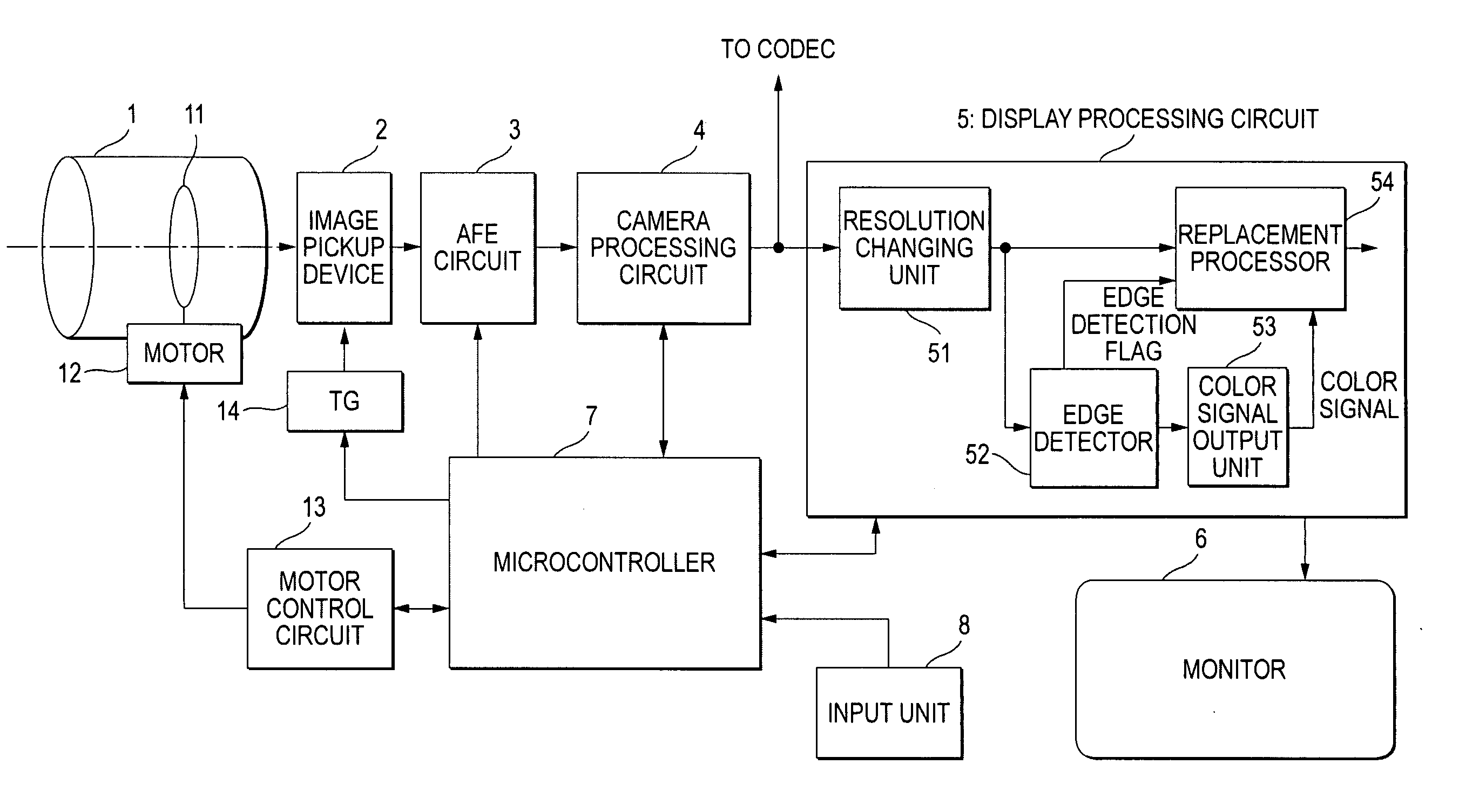
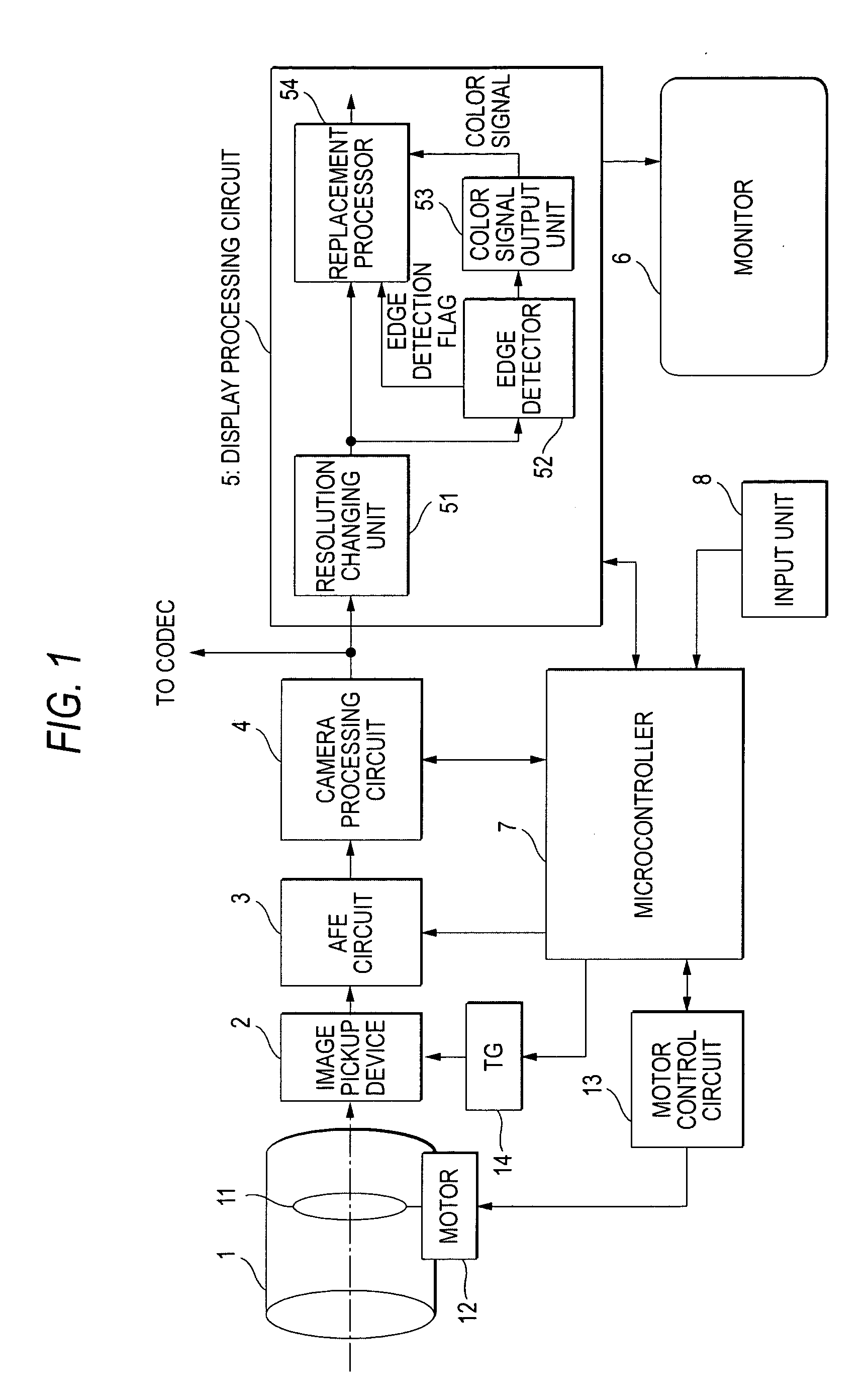
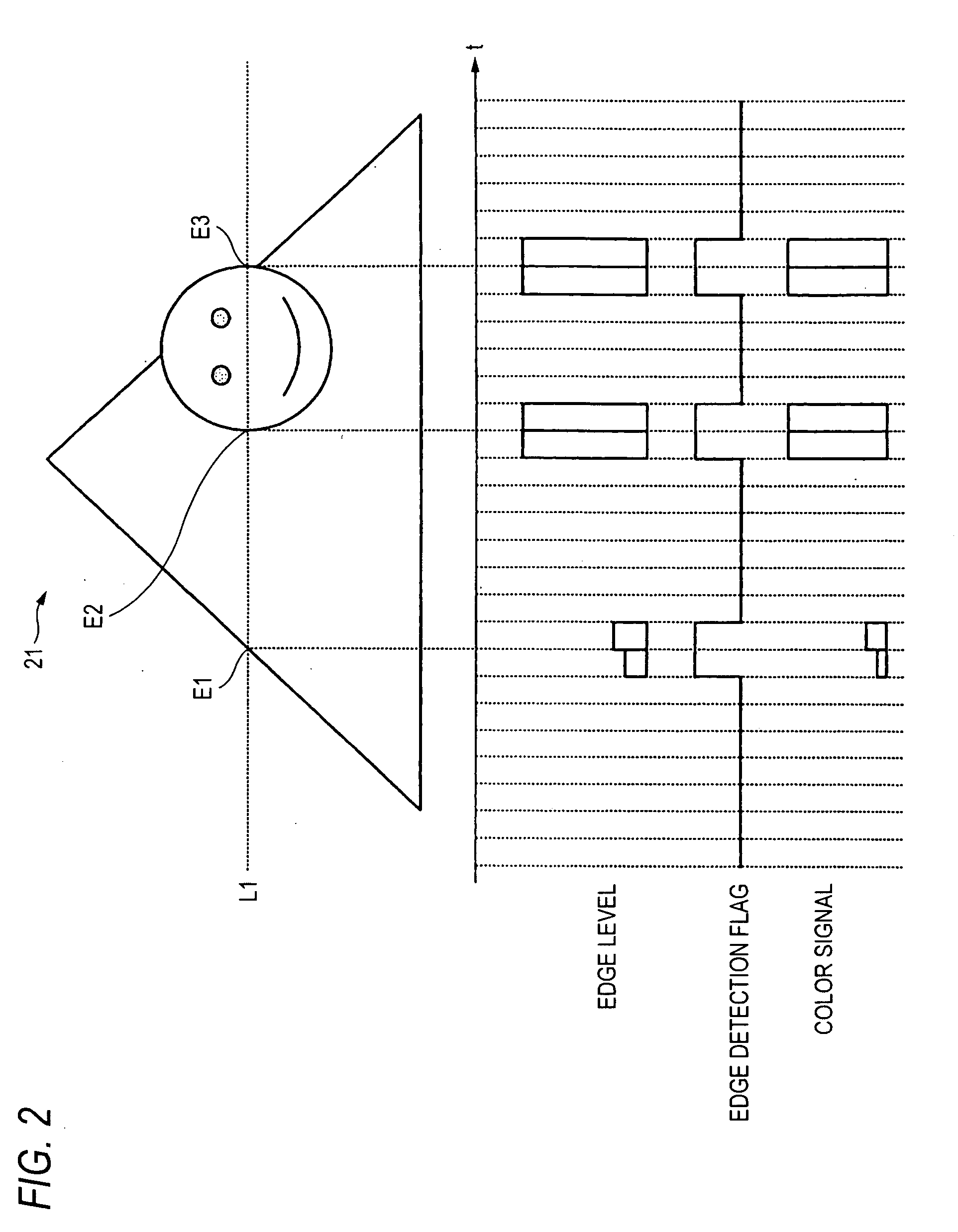
[0015] According to the image pickup apparatus of the invention, in a picked up image displayed on the display means, an edge portion of a subject on which a focusing degree is relatively high is displayed by a predetermined color. Therefore, a user manually taking focus can easily confirm the edge portion of the subject on which the focusing degree is relatively high with his or her eyes and thus more precisely adjust focus.

Problems solved by technology

However, in a technique for showing a focused state for every divided area at the time of adjusting focus by manual operation, when a plurality of subjects exist in the same area, a user cannot differentiate which subject is focused.
However, most monitors provided on the rear surfaces of image pickup apparatuses do not have such a resolution and size that the user can precisely confirm the sharpness of a subject due to the size or the manufacturing cost.
For this reason, it is difficult to precisely adjust focus by manual operation by using a visual observation method.

Method used


Image

  • Image pickup apparatus and display control method
  • Image pickup apparatus and display control method
  • Image pickup apparatus and display control method

Examples


first embodiment

[0050] Next, a specific example of the configuration between the edge detector 52 and the color signal output unit 53 will be described. FIG. 4 is a view showing the configuration of the edge detector and the color signal output unit according to the

[0051] An edge detector 52a shown in FIG. 4 detects the edge level of each pixel by performing a high-pass filtering on the image signal output from the resolution changing unit 51. When the detected edge level is equal to or higher than a predetermined value, the edge detector 52a sets the edge detection flag to a high level. Further, the edge detector 52a calculates a variable n corresponding to the edge level and outputs the calculated variable n to a color signal output unit 53a. The color signal output unit 53a includes a color table 531 in a ROM in which a plurality of color signals used by the replacement processor 54 for replacement at edge portions is stored. The color signal output unit 53a reads, from the color table 531, one ...

second embodiment

[0064]FIG. 6 is a view showing the configuration of an edge detector and a color signal output unit according to a

[0065] An edge detector 52b shown in FIG. 6 detects the edge level of each pixel by performing high-pass filtering on the image signal output from the resolution changing unit 51. When the detected edge level is equal to or higher than a predetermined value, the edge detector 52b determines the pixel to be processes as an edge and sets the edge detection flag to a high level. Further, when the edge detector 52b determines the pixel to be processed as an edge, it outputs a variable DF corresponding to the edge level to a color signal output unit 53b.

[0066] The color signal output unit 53b stores a reference color signal CLR as a reference of color signals used in the replacement processor 54 in a color storage unit 532 composed of a ROM in advance, amplifies the reference color signal CLR so as to have a gain corresponding to the variable DF from the edge detector 52b by...


PUM


Abstract

An image pickup apparatus using a solid image pickup device includes a manual focus adjusting unit configured to control the position of a focus lens in response to a user's input operation; an edge detecting unit configured to detect edge components of each pixel from an image signal obtained by image pickup and to output detection levels of the detected edge components; a color signal replacement unit configured to replace a signal of a pixel corresponding to the detection level or signals of pixels in a predetermined range containing the corresponding pixel on the image signal with a predetermined color signal when the detection level is equal to or higher than a predetermined value; and a display unit configured to display an image based on an output image signal from the color signal replacement unit.

Description

CROSS-REFERENCE TO RELATED APPLICATIONS [0001] The present application claims priority from Japanese Patent Application No. JP 2005-243585 filed on Aug. 25, 2005, the disclosure of which is hereby incorporated by reference herein. BACKGROUND OF THE INVENTION [0002] 1. Field of the Invention [0003] The present invention relates to an image pickup apparatus for capturing an image by using a solid image pickup device and a method of controlling the display of the same. More specifically, the present invention relates to an image pickup apparatus having a manual focusing function and a method of controlling the display of the same. [0004] 2. Description of the Related Art [0005] Known image pickup apparatuses using a solid image pickup device, such as a digital still camera and a digital video camera, generally have an auto focusing (AF) function of automatically bring an image into focus. However, in recent years, many image pickup apparatuses have a manual focusing function of manuall...

Claims


Application Information

Patent Timeline
IPC IPC(8): G03B13/00
CPCH04N5/23293H04N5/23212H04N23/673H04N23/63H04N23/67G06T7/13
Inventor YAMADA, TOKUICHIROKUME, TSUTOMU
Owner SONY CORP
Learn More