

Electrical connector
- Summary
- Abstract
- Description
- Claims
- Application Information
AI Technical Summary
Benefits of technology
Problems solved by technology
Method used
Image

Examples
Embodiment Construction
[0026] The present invention will now be described in more detail hereinafter with reference to the accompanying drawings that show various embodiments of the invention.
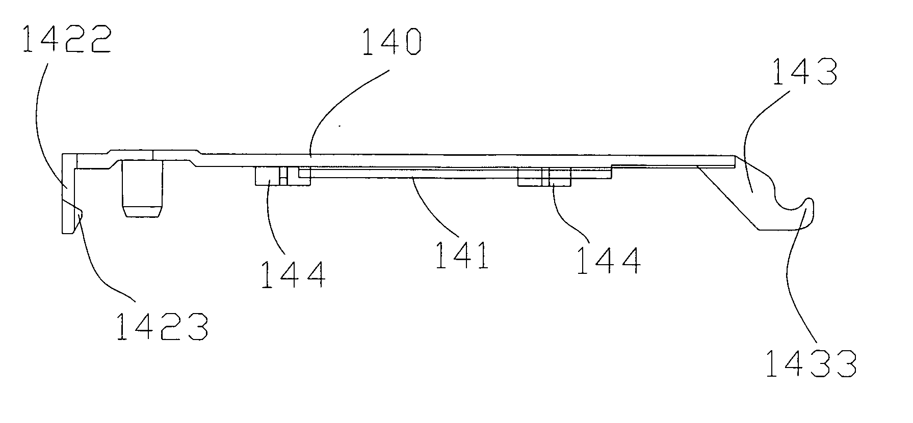
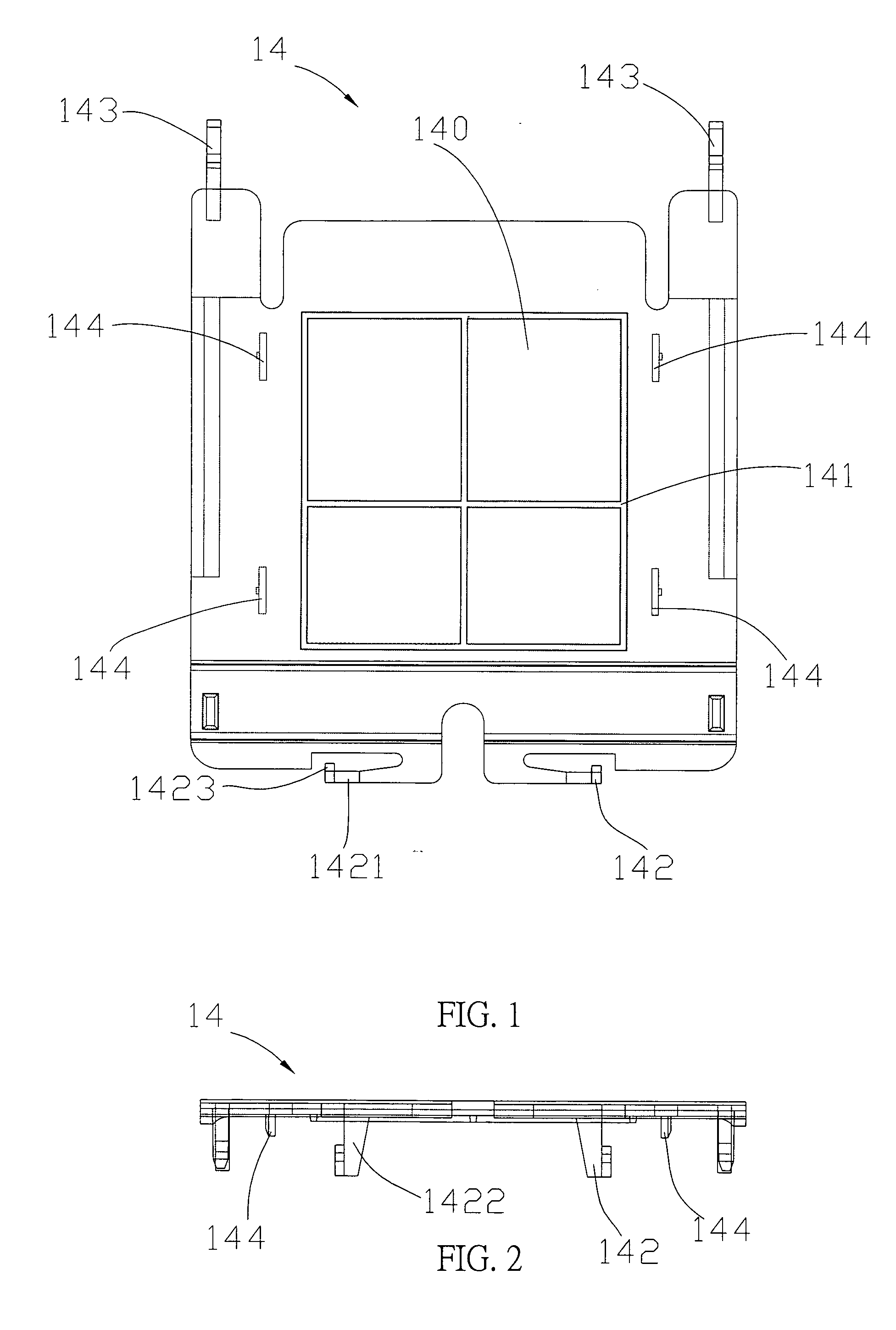
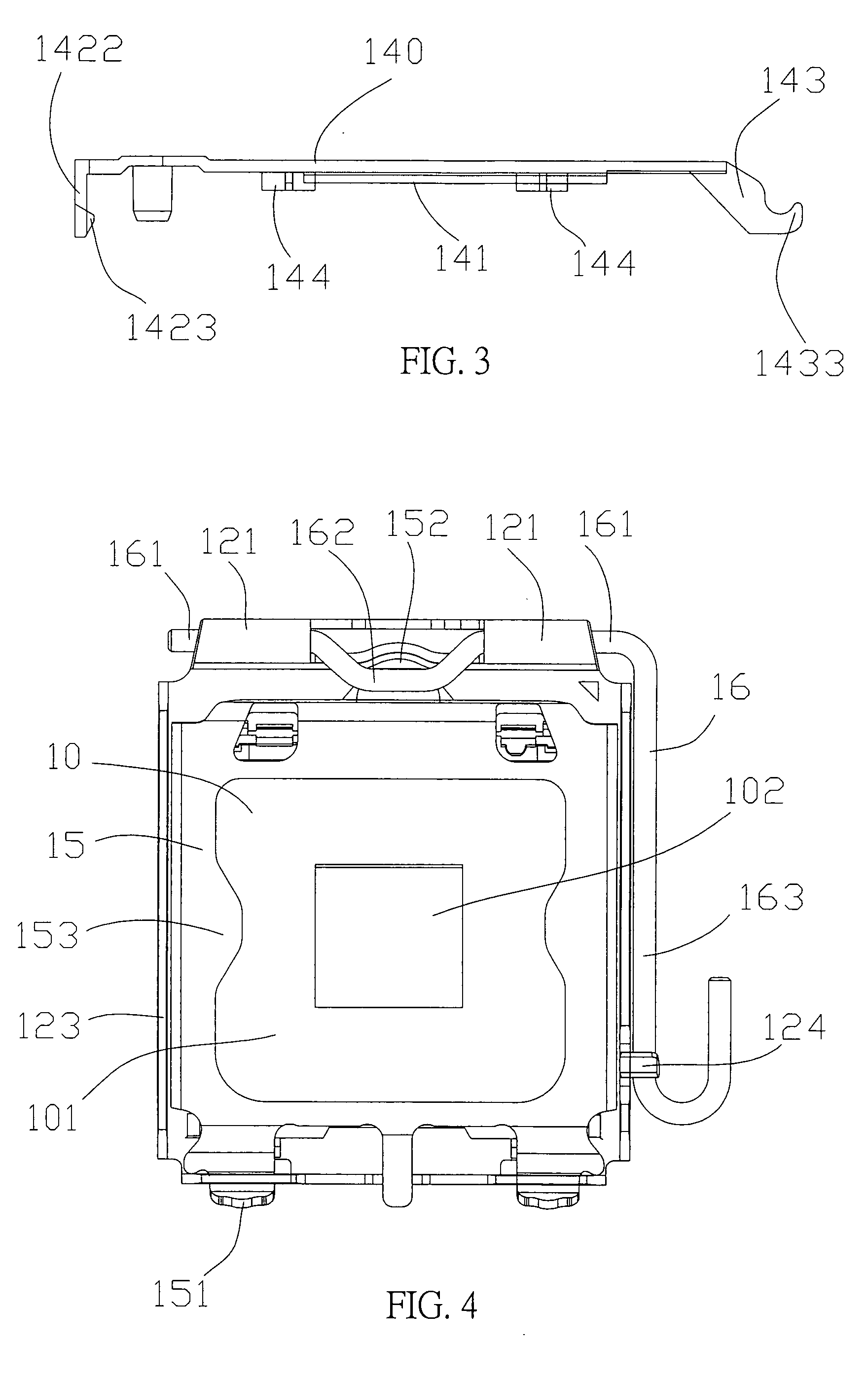
[0027] Referring to FIGS. 1 to 8 for the electric connector 1 of the invention used for connecting a chip module (not shown in the figure) comprises an insulating body 10, an electric conducting terminal (not shown in the figure), a latch base 12, an attaching cover 14, a cover 15 separately and pivotally coupled to both ends of the latch base 12 for pressing the chip module, and a lever 16 disposed on the latch base 12 for pressing the cover 15.
[0028] The insulating body 10 includes a retaining portion 101 disposed thereon for carrying the chip module (not shown in the figure), and the retaining portion 101 includes a plurality of terminal containing holes (not shown in the figure) disposed thereon for containing the electric conducting terminal (not shown in the figure), and the insulating body at its central pos...
PUM
 Abstract
Description
Claims
Application Information