
Directional drilling executing mechanism based on three-speed drill bit

A technology of directional drilling and actuator, applied in directional drilling, drilling equipment, drill pipe, etc., can solve the problems of push rod damage, high cost, and narrow use range.

Inactive Publication Date: 2016-08-17
柳超
View PDF0 Cites 7 Cited by
  • Summary
  • Abstract
  • Description
  • Claims
  • Application Information

AI Technical Summary

Problems solved by technology

On the one hand, the former requires a motor to drive the oil pump to produce hydraulic oil with pressure. Because of the oil pressure, oil leakage is often prone to occur, and the requirements for oil cylinder technology and sealing technology are relatively high, resulting in high cost and complicated mechanism; for the latter, use Driven by a motor, the structure is simpler than the former, but because of the meshing transmission between the gear and the screw, when the load changes suddenly, it is easy to cause fatal damage to the push rod, that is, the range of use is narrow

Method used


Image

  • Directional drilling executing mechanism based on three-speed drill bit
  • Directional drilling executing mechanism based on three-speed drill bit
  • Directional drilling executing mechanism based on three-speed drill bit

Examples


Embodiment Construction

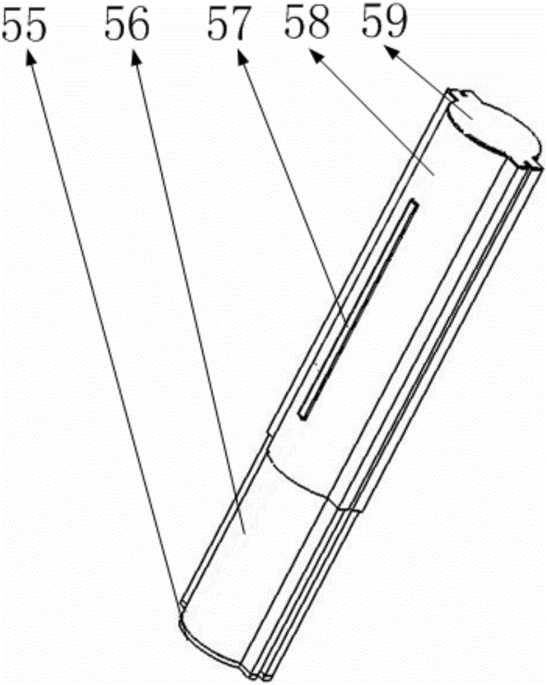
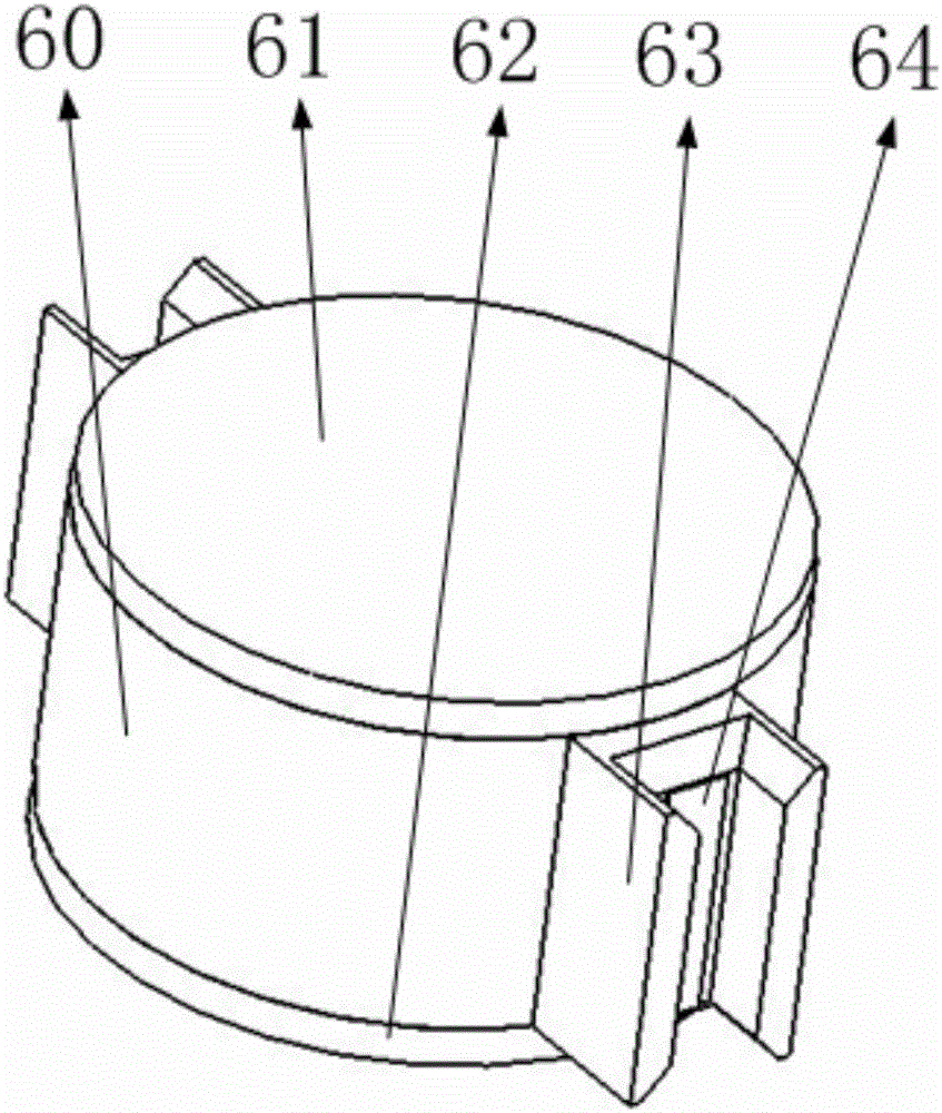
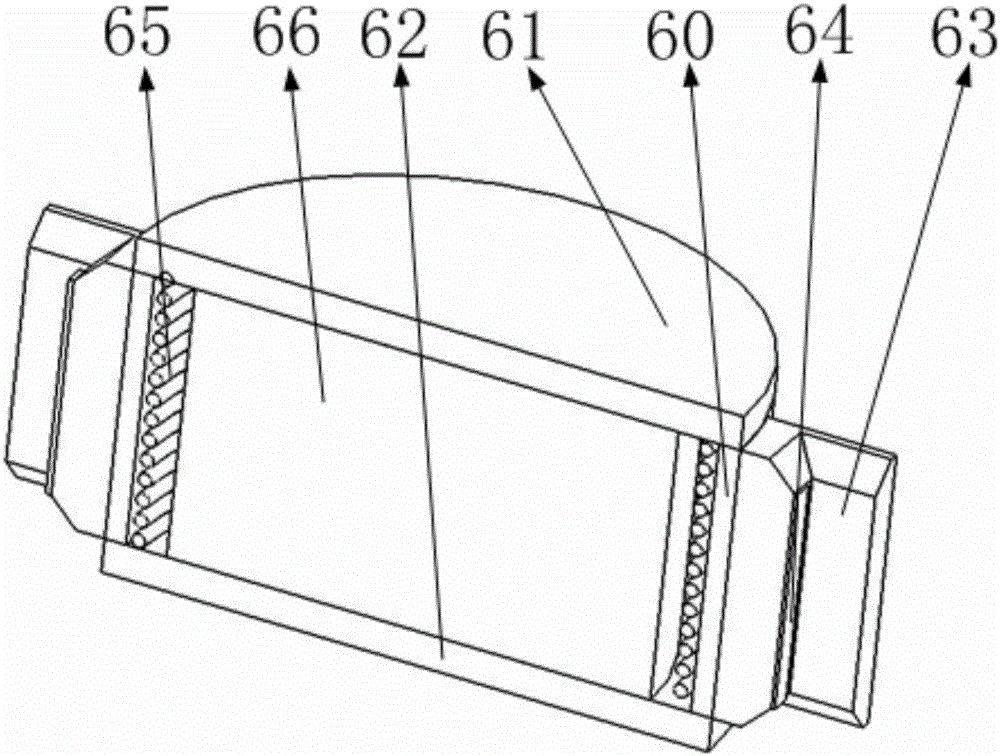
[0058] Such as Figure 22 , 24 , 32, it includes a drill string, a drill bit, a motor shaft, a pressure support plate, a pressure electromagnetic telescopic rod, a connection structure, a second positioning mechanism, a motor, a first positioning mechanism, an electromagnetic telescopic rod support plate, and a moving ring , reinforcement ring, rotating pair of pressure electromagnetic telescopic rod, universal joint, among which Figure 22 As shown, the drill bit is installed at one end of the drill rod, and the drill rod is installed at the center hole of the pressure support plate through the bearing, as shown in Figure 25 As shown, the reinforcement ring is installed on the underside of the pressure support plate, such as Figure 32 , 33 As shown, the drill bit and the drill rod are connected to the motor shaft through the connecting structure and the universal joint; Figure 25 As shown, one end of a pressure-applying electromagnetic telescopic rod is installed on th...


PUM


Abstract

The invention belongs to the technical field of drilling, and particularly relates to a directional drilling executing mechanism based on a three-speed drill bit. The directional drilling executing mechanism comprises a drill bit drill string, a drill bit, a pressure exerting support plate, pressure exertion electromagnetic telescopic rods, a connecting structure, a positioning mechanism, a motor, an electromagnetic telescopic rod support plate, rotating pairs and a universal joint, wherein the drill bit is connected with the motor through the drill bit drill string, the connecting structure, the universal joint and a motor rotating shaft; through the design of the universal joint, the drill bit drill string can still be driven to rotate by the motor after forming a certain angle relative to the motor rotating shaft; the drill bit drill string is arranged on the pressure exerting support plate; and the three rotating pairs are added to the installation of the two pressure exertion electromagnetic telescopic rods on the pressure exerting support plate and the pressure exerting telescopic rod support plate. By adopting such a design, when the drill bit is enabled to do forward drilling, the drill bit is allowed to form a certain angle relative to the motor. The angle of the drill bit drill string and the motor rotating shaft can be controlled for directional drilling, and high practicability is realized.

Description

Technical field [0001] The invention belongs to the technical field of drilling, and in particular relates to a directional drilling actuator based on a three-speed drill bit. Background technique [0002] At present, drilling equipment often adopts uphole power output, and the power is transmitted to the downhole drill bit through the drill string. When the depth of the drilled well is required to be very deep, an ultra-long-distance drill string is often spliced ​​by multiple drill strings. When the deep well being drilled is directional drilling, the shaft axis will have one or more inflection points, and the drill string will need to consider the transmission structure at the inflection points, which increases the complexity of the drilling equipment; therefore, designing a drilling equipment for downhole energy supply will This problem can be better solved, and adding a structure that can control the direction of the drill bit on the basis of independent energy supply ...

Claims


Application Information

Patent Timeline
Patent Type & Authority Applications(China)
IPC IPC(8): E21B7/04H02N11/00
CPCE21B7/04E21B10/43E21B17/028E21B17/03E21B17/07E21B17/10H02N11/00
Inventor 柳超
Owner 柳超
Learn More