
Display driver apparatus, and electro-optical device and electronic equipment using the same

a technology of display driver and driver device, which is applied in the direction of instrumentation, electric programme control, program control, etc., can solve the problems of complex part management and additional complications, and achieve the effect of increasing the general applicability and allowing selective change of the number of display gradients availabl

Inactive Publication Date: 2006-08-01
BOE TECH GRP CO LTD
View PDF8 Cites 9 Cited by
  • Summary
  • Abstract
  • Description
  • Claims
  • Application Information

AI Technical Summary

Benefits of technology

[0006]Therefore, it is an object of the present invention to provide a display driver apparatus with increased general applicability, in which the number of display gradients available can be selectively changed.

Problems solved by technology

As a result, parts management has become complex, because different parts may have to be prepared for each of the display driver apparatuses with different specifications.
There are additional complications as well.

Method used


Image

  • Display driver apparatus, and electro-optical device and electronic equipment using the same
  • Display driver apparatus, and electro-optical device and electronic equipment using the same
  • Display driver apparatus, and electro-optical device and electronic equipment using the same

Examples


Embodiment Construction

[0021]Embodiments of the present invention are described below in detail with reference to the accompanying drawings.

Display Driver Apparatus

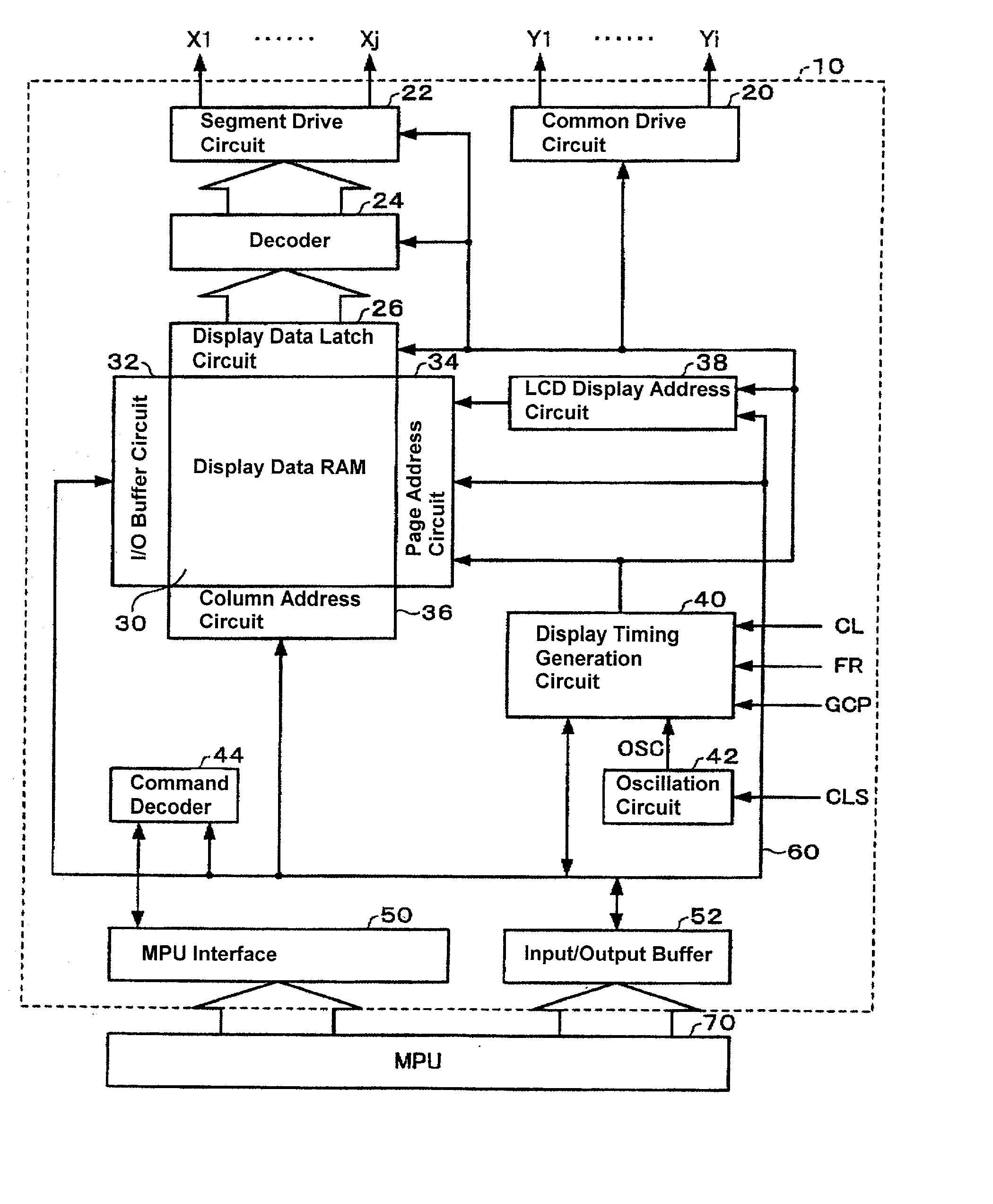
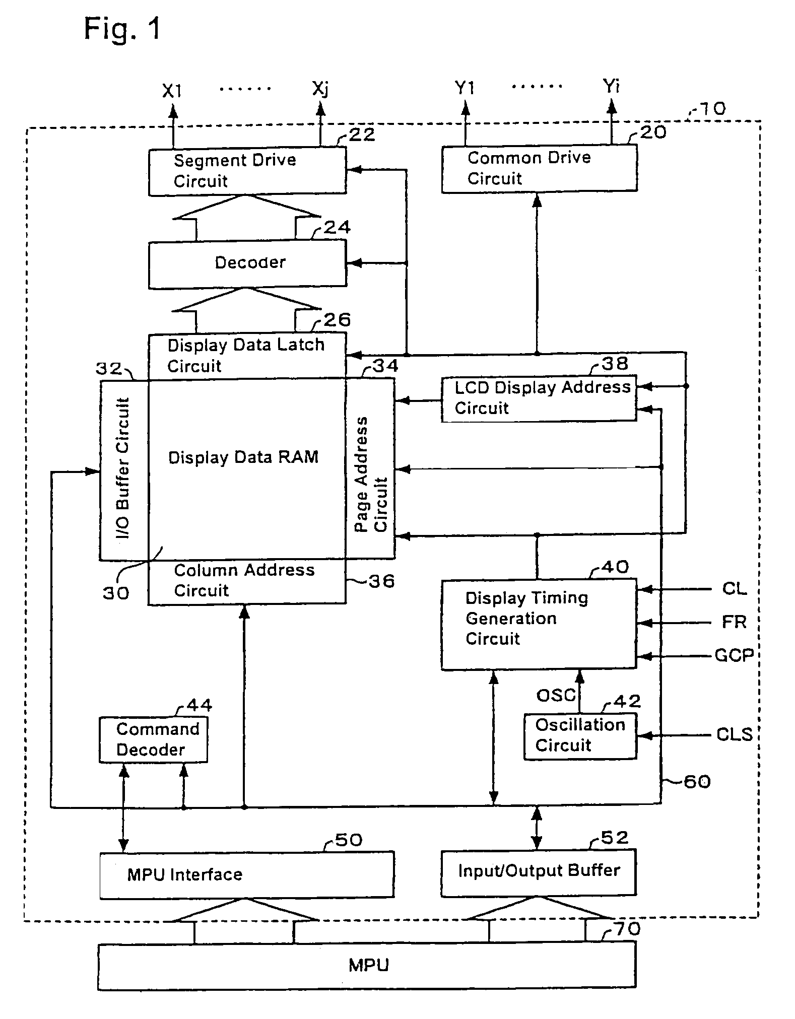
[0022]A display driver apparatus 10 shown in FIG. 1, which is formed from an IC chip, has components for driving a liquid crystal device (LCD), such as, a common drive circuit 20, a segment drive circuit 22, a decoder 24, a display data latch circuit 26, a display data RAM 30, an input / output (I / O) buffer circuit 32, a page address circuit 34, a column address circuit 36, an LCD display address circuit 38, a display timing generation circuit 40, an oscillation circuit 42, an MPU interface circuit 50 and an input / output buffer 52.

[0023]The MPU interface circuit 50 has multiple input terminals for inputting various signals from an external MPU 70. The input terminals provided include a chip select terminal, a data recognition terminal, a data bus latch terminal, a data taking terminal, a reset terminal and a parallel-serial input switching termin...


PUM

PropertyMeasurementUnit
voltageaaaaaaaaaa
output voltageaaaaaaaaaa
power consumptionaaaaaaaaaa

Abstract

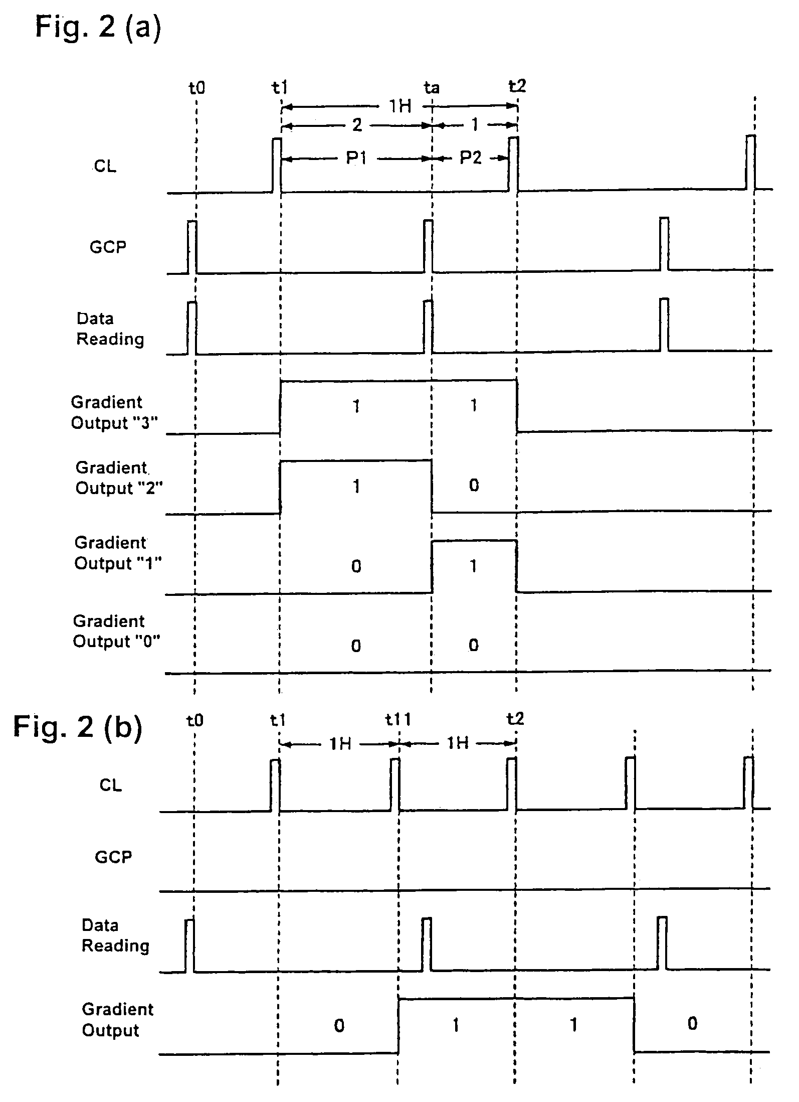
A display driver capable of operating in any one of multiple gradient display modes drives a liquid crystal panel in which the first L common electrodes are simultaneously selected in a first selection period and successive groups of L common electrodes are simultaneously selected in successive selection periods. 8-bit display data for each segment electrode are simultaneously read from a display data RAM and latched. First and second sub-decoders decode divided upper and lower four bits of the 8-bit display data, respectively. In a first mode, the data is for a four gradient display for each of four pixels on each segment electrode. In a second mode, the data is for a two gradient display for each of eight pixels on each segment electrode.

Description

BACKGROUND OF THE INVENTION[0001]1. Field of the Invention[0002]The present invention relates to a display driver apparatus, and an electro-optical device and an electronic equipment using the same.[0003]2. Description of the Related Art[0004]In recent years, display driver apparatuses have been implemented in hand-held telephones, hand-held data terminals and gaming apparatuses to perform screen display control. However, because the required display gradient between and among such devices varies, depending on the purpose or application of use, different display driver apparatuses having different gradient displays are individually manufactured for a particular purpose and application. Less expensive display drivers are incorporated into lower priced devices. Others are employed to provide lower power consumption. Still others offer higher image quality.[0005]Thus, in recent years, different types of display driver apparatuses with different specifications regarding the number of gr...

Claims


Application Information

Patent Timeline
Patent Type & Authority Patents(United States)
IPC IPC(8): G09G5/00G02F1/133G05B19/42G09G3/20G09G3/36
CPCG09G3/3622G09G3/3611G09G3/2018G09G2310/0205
Inventor KOBAYASHI, KAZUO
Owner BOE TECH GRP CO LTD
Learn More