Electrical connector

Inactive Publication Date: 2007-03-08
HIROSE ELECTRIC GROUP
View PDF9 Cites 9 Cited by
  • Summary
  • Abstract
  • Description
  • Claims
  • Application Information

AI Technical Summary

Benefits of technology

[0021] With the electrical connector of the invention, it is possible to improve contact reliability of the terminal while achieving good high-frequency characteristic

Problems solved by technology

However, the one-point contact tends to cause a reliability problem.
Further, when a conventional connector achieves a low-profile design, a receptacle thereof tends to have low strength against a fitting operation relative to a mate connector, i.e., a plug.
As a result, when the connector is fitted to a mate connector, a fitting opening tends to be deformed, thereby deteriorating contact reliability.
However, when the ground terminal is provided, a

Method used


Image

  • Electrical connector
  • Electrical connector
  • Electrical connector

Examples


Example

[0034] Hereunder, embodiments of the present invention will be explained with reference to the accompanying drawings.

[0035] According to the present invention, an electrical connector includes a pair of connectors, i.e., a connector to be connected to a cable (a plug connector) and a connector to be connected to a board (a receptacle connector). The plug connector can be fitted to the receptacle connector so as to freely attach / detach.

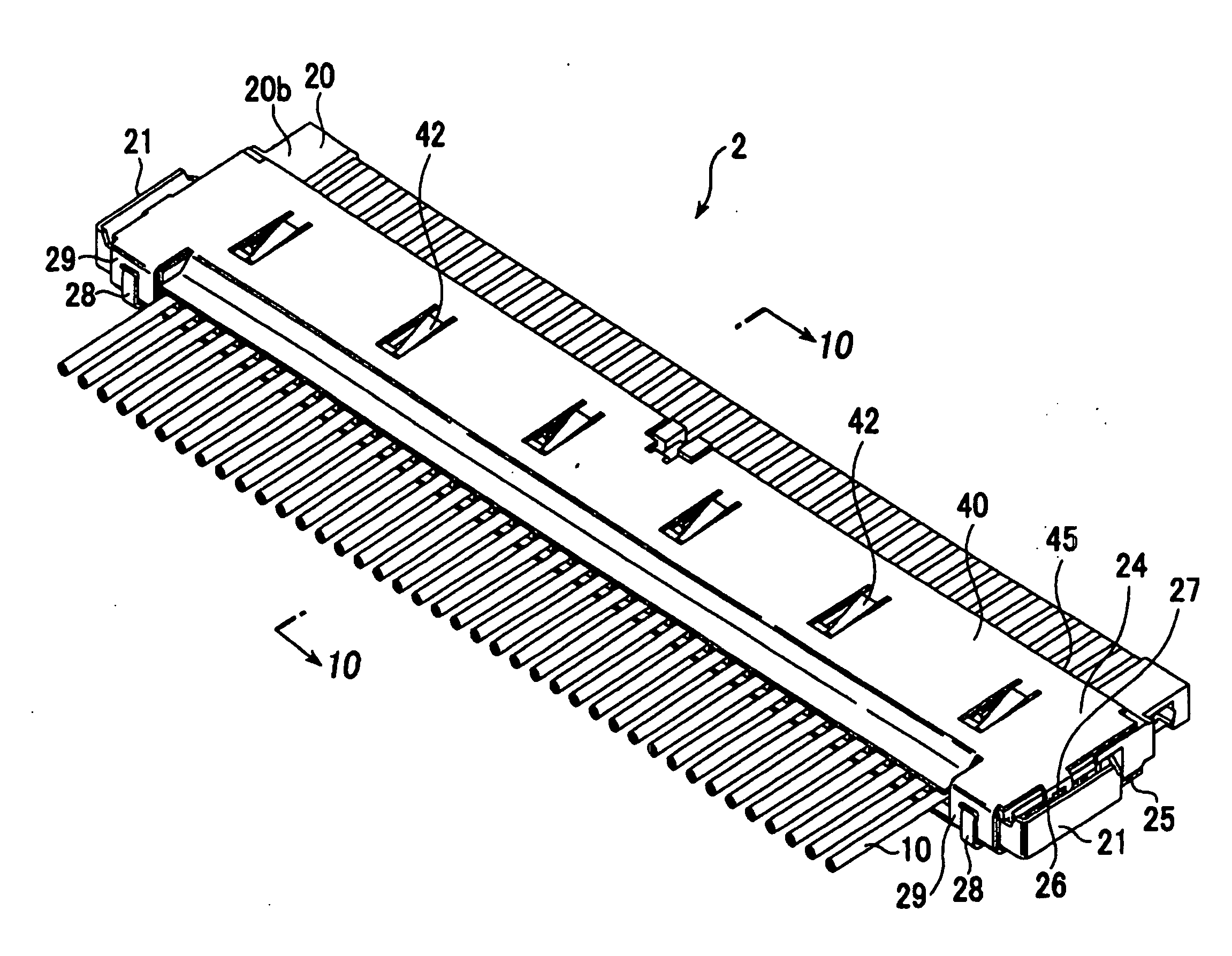
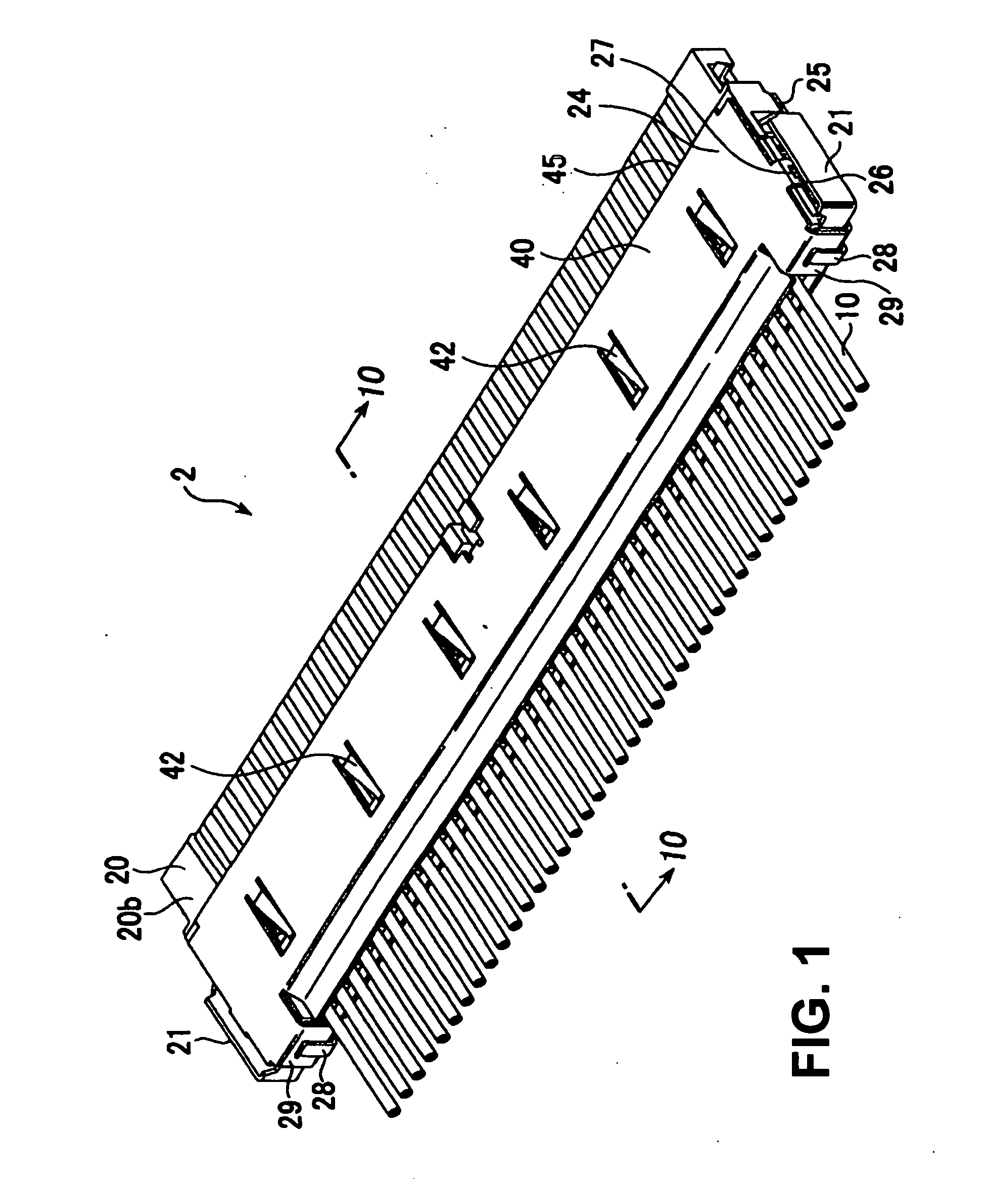
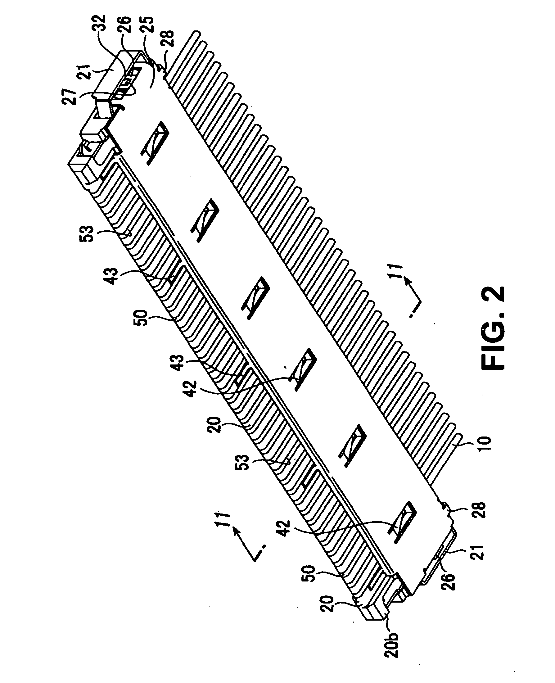
[0036]FIG. 1 is a perspective view showing an upper surface of a plug according to an embodiment of the present invention. FIG. 2 is a perspective view showing a bottom surface of the plug according to the embodiment of the present invention. FIG. 3 is a perspective view showing the plug shown in FIG. 1 in a state that an upper plug shell is removed. FIG. 4 is a perspective view showing the plug shown in FIG. 3 in a state that cables are removed. FIG. 7 is a perspective view showing an upper surface of a receptacle according to the embodiment of the ...


PUM


Abstract

An electrical connector to be connected to a cable includes a first housing having a casing with a substantially rectangular shape and a fitting section protruding from the casing in a direction that the electrical connector is fitted to a mate connector; a first shell covering the casing; and a first terminal arranged in the fitting section. The first terminal has contact sections at upper and lower sides of one end thereof for contacting with a terminal of the mate connector, and a connecting section at the other end thereof for connecting with a core wire of the cable. It is arranged such that a distance from the contact section at the upper side to the connecting section is substantially same as a distance from the contact section at the lower side to the connecting section.

Description

BACKGROUND OF THE INVENTION [0001] 1. Field of the Invention [0002] The present invention relates to an electrical connector of a low-profile mounting type for connecting a cable to a board. [0003] 2. Description of Related Art [0004] For example, Japanese Patent Publication No. 2001-307822 discloses an electrical connector of a low-profile mounting type. In this type of electrical connector, high frequency characteristics are required. It is also necessary to reduce a size of a connector, especially a height thereof, to achieve a low-profile design. [0005] In order to meet the requirements, in a conventional connector, a terminal includes a one-point contact. However, the one-point contact tends to cause a reliability problem. Further, when a conventional connector achieves a low-profile design, a receptacle thereof tends to have low strength against a fitting operation relative to a mate connector, i.e., a plug. As a result, when the connector is fitted to a mate connector, a fitt...

Claims


Application Information

Patent Timeline
IPC IPC(8): H01R9/03
CPCH01R12/716H01R13/58H01R13/646
Inventor FUKUSHIMA, TAKESHISAKATA, TSUYOSHI
Owner HIROSE ELECTRIC GROUP
Why Eureka
Try Eureka